
Static mixer for pipeline

A static mixer and mixer technology, which is applied in the directions of fluid mixers, mixers, chemical instruments and methods, can solve the problems of large fluid flow resistance, high manufacturing cost, and high operating energy consumption, and achieve long-distance energy consumption. Low, save the amount of investment, good mixing effect

Inactive Publication Date: 2012-05-09
ZHEJIANG MARINE DEV RES INST
View PDF3 Cites 12 Cited by
  • Summary
  • Abstract
  • Description
  • Claims
  • Application Information

AI Technical Summary

Problems solved by technology

[0004] The present invention mainly solves the technical problems existing in the prior art such as complex structure, high manufacturing cost, large flow resistance of fluid in the pipeline, and high energy consumption in operation, and provides a pipeline static pipeline with simple structure, easy manufacture, and low energy consumption in operation. mixer

Method used


Image

  • Static mixer for pipeline
  • Static mixer for pipeline
  • Static mixer for pipeline

Examples


Embodiment 1

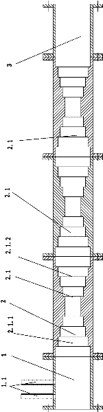
[0017] Such as figure 1 As shown, the present invention includes a mixer pipeline body, and the mixer pipeline body includes a water inlet dosing area 1, a water medicine mixing area 2 and a water outlet area 3; two dosing pipes 1.1 are fixed on the water inlet dosing area 1; The drug mixing area 2 is composed of three sequentially connected combined flow channel areas 2.1, and each combined flow channel area 2.1 includes a tapered flow channel 2.1.1 and a tapered flow channel 2.1.2, the tapered flow channel 2.1. The small end of 1 is docked with the small end of the diverging channel 2.1.2; the converging channel 2.1.1 and the diverging channel 2.1.2 are both frustum-shaped channels, that is, their axial sections are all isosceles trapezoidal, The surfaces of the converging flow channel 2.1.1 and the diverging flow channel 2.1.2 are each provided with a four-stage stepped ring-type agitation structure to prevent the formation of a laminar flow layer on the surface of the flow...

Embodiment 2

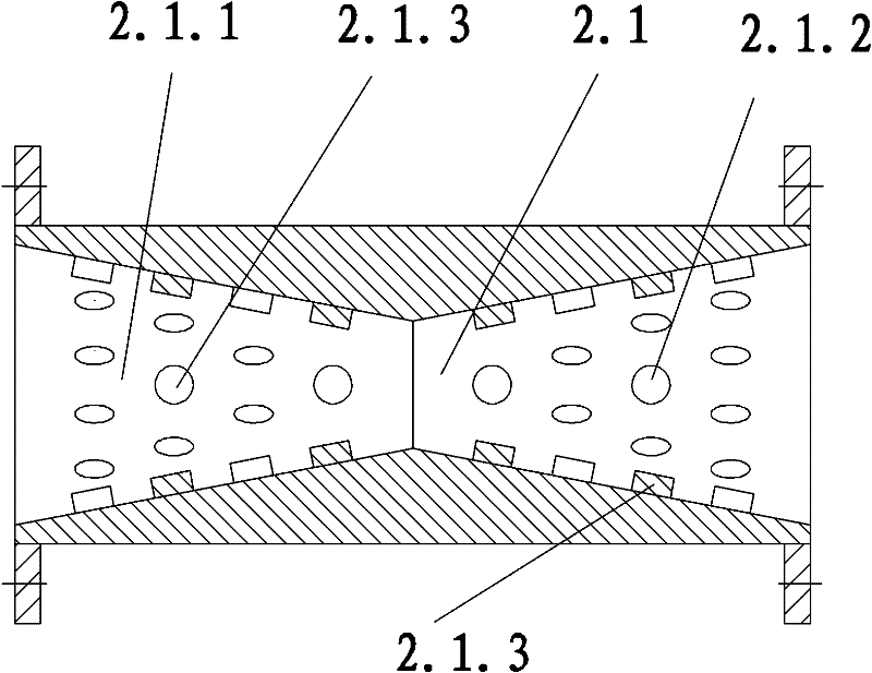
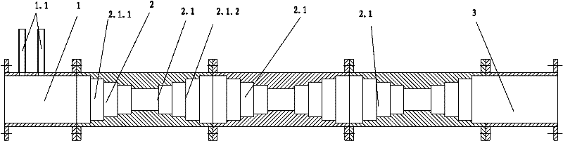
[0019] Such as figure 2 As shown, the structural difference between Embodiment 2 and Embodiment 1 is that some protrusions 2.1 are provided on the surfaces of the converging flow passage 2.1.1 and the diverging flow passage 2.1.2 of the combined flow passage area 2.1 of Embodiment 2. .3 Constitute a turbulent flow structure to prevent the formation of a laminar layer on the surface of the flow channel. These protrusions 2.1.3 form several raised rings on the corresponding flow channel surface along the axis of the flow channel. The same tapered flow channel 2.1 .1 and the protrusions 2.1.3 on two adjacent protrusion rings on the surface of the same diverging channel 2.1.2 are distributed alternately. In this embodiment, the protrusions 2.1.3 are cylindrical protrusions, and each protrusion 2.1.3 is welded together with the surfaces of the tapered flow channel 2.1.1 and the divergent flow channel 2.1.2. In addition to the cylindrical protrusions used in this example, the prot...


PUM


Abstract

The invention relate to a static mixer for a pipeline, which is used in a flocculent settling device in water treatment equipment and enables flocculent and raw water to be fully mixed. The static mixer for the pipeline solves the technical problems of complex structure, high manufacture cost and high operation energy consumption in the prior art, has the advantages of simple structure and low operation energy consumption and easy manufacture. The static mixer for the pipeline comprises a mixer pipeline body, wherein the mixer pipeline body comprises a water and medicine mixing zone; a runner of the water and medicine mixing zone is formed by alternatively connecting a plurality of tapered runners and divergent runners along the water flow direction; and the surface of the water and medicine mixing zone is provided with a flow stirring structure. When the static mixer for a pipeline works, the speed and the direction of the water flow on each position in the water and medicine mixing zone are in the constantly-changing process, the flow stirring structure can effectively prevent from forming a stable laminar flow layer on the surface of the runner, which is favorable for generating high-strength turbulence micro-vortex on each position in the water and medicine mixing zone, so that the mixing effect of the raw material and the flocculent is improved, and the dispensing quantity of the flocculent is saved.

Description

technical field [0001] The invention relates to the technical field of water treatment, in particular to a pipeline static mixer used in a flocculation and sedimentation device to fully mix flocculant and raw water. Background technique [0002] In the flocculation and sedimentation device system of water treatment, a mixing device for flocculant and raw water is often installed on the raw water inlet pipe of the flocculation and sedimentation device, which is used to fully and uniformly mix the raw water and flocculant to form a microfloc before entering The main body of the flocculation-sedimentation device performs further flocculation-sedimentation treatment. [0003] The Chinese patent document published on August 11, 2010 with the publication number CN 201543393U and titled "A Pipeline Static Mixer Device" discloses a pipeline static mixer, which mainly includes a drug delivery tube and a tube body. Be: also comprise diffusion cone cap, reducer, mixing orifice plate, ...

Claims


Application Information

Patent Timeline
IPC IPC(8): B01F5/00C02F1/52
Inventor 范会生王波张海春陆阿定郁小芬孙兆栋孙保库
Owner ZHEJIANG MARINE DEV RES INST
Features
  • Generate Ideas
  • Intellectual Property
  • Life Sciences
  • Materials
  • Tech Scout
  • Unparalleled Data Quality
  • Higher Quality Content
  • 60% Fewer Hallucinations
Learn More