Waste heat cycling heating power circulating system device of engine

A thermodynamic cycle system and waste heat recovery technology, which is applied in the direction of steam engine devices, engine components, combustion engines, etc., can solve the problems of low decomposition temperature of organic working fluid, increase in efficiency, limitations, etc., and achieve high waste heat recovery efficiency.

Inactive Publication Date: 2012-05-09
TIANJIN UNIV
View PDF4 Cites 15 Cited by
  • Summary
  • Abstract
  • Description
  • Claims
  • Application Information

AI Technical Summary

Problems solved by technology

If an organic working fluid suitable for the waste heat cycle is used, the efficiency will increase and the volume o

Method used


Image

  • Waste heat cycling heating power circulating system device of engine
  • Waste heat cycling heating power circulating system device of engine

Examples


Example Embodiment

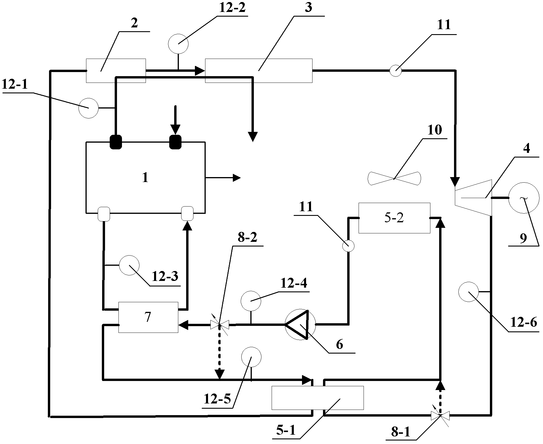
[0013] The system structure and working process of the present invention will be further described below in conjunction with the drawings and embodiments. It should be noted that this embodiment is narrative rather than limiting, and does not limit the protection scope of the present invention.

[0014] The engine waste heat recovery thermodynamic cycle system device, its system composition and structural features are: the exhaust pipe of the engine 1 is connected in series to the thermoelectric generator 2 and the evaporator 3; the working fluid side of the thermoelectric generator is connected in series to the evaporator through the pipeline 3. The expander 4, the high temperature side of the regenerator 5-1, the condenser 5-2, the working medium pump 6, the working medium side of the preheater 7, and the low temperature side of the regenerator 5-1 return to the temperature difference generator Electrical appliances constitute a closed loop system. A first bypass valve 8-1 is ...


PUM


Abstract

The invention discloses a waste heat cycling heating power circulating system device of an engine. The system composition is that an exhaust pipe of the engine is in series connection with a thermoelectric generator and an evaporator. The working medium side of the thermoelectric generator is in series connection with the evaporator, an expander, a heat regenerator, a condenser, a working medium pump and the working medium side of a preheater in sequence through pipelines and returns to the thermoelectric generator through the low-temperature side of the heat regenerator, and a closed circuit circulation system is formed. Bypass valves are respectively arranged between an inlet on the high-temperature side of the heat regenerator and an outside outlet pipeline and between an inlet of the preheater and the outside outlet pipeline. By the utilization of an automatic electrical control system, temperature and pressure of six points of a heating power circulating system are monitored, and the opening and closing of two bypass valves are controlled so that an optimum flow of a working medium of the system is ensured. The waste heat cycling heating power circulating system device overcomes the shortcomings of waste heat recycling of the engine in the prior art, and achieves step utilization of waste heat of the engine and the purposes of improving economy of fuel oil of the engine and reducing emission.

Description

technical field [0001] The invention belongs to waste heat utilization technology, and in particular relates to a thermodynamic cycle system for recovering waste heat of an engine. technical background [0002] As we all know, only a part of the energy released by engine fuel combustion is converted into mechanical work to drive the output shaft, while most of the rest of the heat energy is discharged as waste heat. At present, the thermal efficiency of the engine is generally 30%-45% for diesel engines, and 20%-30% for gasoline engines. It shows that about 2 / 3 of the energy enters the surrounding environment through the cooling system, lubrication system and exhaust, causing serious energy waste and polluting the environment. Therefore, how to improve fuel utilization and reduce exhaust emissions has become the key to energy saving and emission reduction in the engine industry. main problem. It can be seen that the recovery of engine exhaust waste heat is a key technology...

Claims


Application Information

Patent Timeline
IPC IPC(8): F01K23/14F01N5/02
CPCY02T10/16Y02T10/12
Inventor 舒歌群赵健田华卫海桥梁兴雨赵智博梁友才于国鹏刘丽娜
Owner TIANJIN UNIV
Why Eureka
Try Eureka