
Gear engine and drive system

A technology of engines and gears, applied in the field of engine systems, can solve the problems of easy evaporation of liquid, lower engine efficiency, and easy generation of back pressure, etc., to achieve high speed and smooth operation

Inactive Publication Date: 2012-05-09
张金铭
View PDF2 Cites 3 Cited by
  • Summary
  • Abstract
  • Description
  • Claims
  • Application Information

AI Technical Summary

Problems solved by technology

The disadvantage is that the liquid used to generate bubbles is easy to evaporate, and it is difficult to form bubbles in a high temperature environment
If a high temperature resistant liquid is used, it may release harmful gas in a high temperature environment, which is not good for the environment
There is a method of recovering exhausted energy mentioned in "Recovering Compressed Energy Generator System" CH200910241486.7, which uses high-pressure gas to do work. The disadvantage is that in the process of recovering exhausted energy, it is easy to generate back pressure and reduce the efficiency of the engine.

Method used


Image

  • Gear engine and drive system
  • Gear engine and drive system
  • Gear engine and drive system

Examples


Embodiment Construction

[0031] The real-time mode of the present invention will be described in detail below in conjunction with the accompanying drawings.

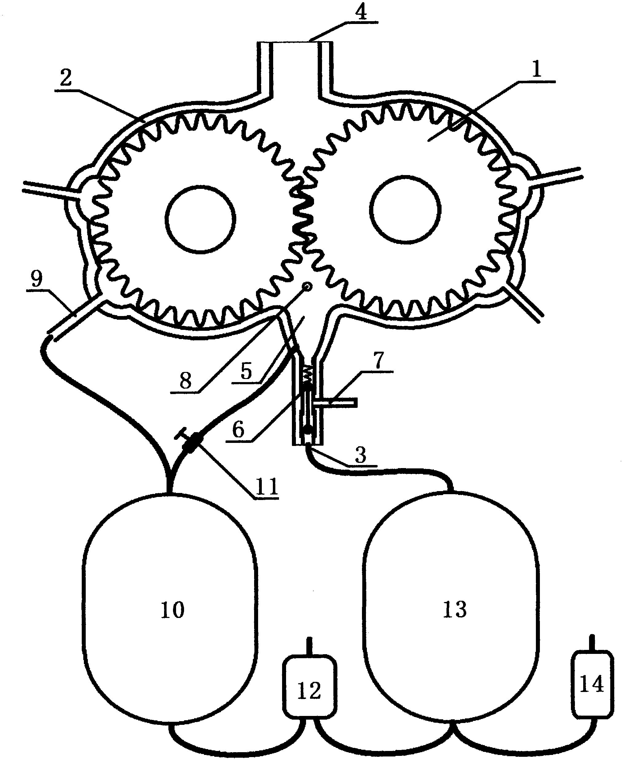
[0032] figure 1 is a schematic diagram of a geared engine.

[0033] 1. The gear motor, including: a double gear 1, a housing 2, an inlet 3, and an outlet 4, which are similar in structure to those in the gear pump, and are characterized in that: on the inner side of the housing 2, the inlet 3 and the two gears 1 are set as The combustion chamber 5 and the inlet 3 are connected to the compressed air tank 13 through the one-way valve 6 , the fuel nozzle 7 is arranged in the inlet 3 , and the ignition device 8 is arranged in the combustion chamber 5 .

[0034] The fuel injection pipe is set in the intake pipe. Although the fuel flows through the compressed air, it enters the combustion chamber through the one-way valve. After ignition, the pressure in the combustion chamber increases, the one-way valve closes, and the gas in the combustion chamber...


PUM


Abstract

The invention discloses a gear engine and drive system. The invention relates to an engine system. An existing triangle rotator engine cannot output high torque at a high speed or a low speed, thus the existing triangle rotator engine cannot satisfy the actual demands and cannot be widely used. The purpose of the invention is to provide a power system satisfying the modern demands, which overcomes the above-mentioned many defects, and can output the high torque under a high or low-speed operating state. The power system has the characteristics of high efficiency and a plurality of energy uses. The power system comprises the four following main parts of: firstly, a gear engine; secondly, an energy recycling system; thirdly, a gear pneumatic motor; and fourthly, a gear engine and drive system, wherein the gear engine and drive system comprises a gas storage tank and a gear pump, and is characterized in that a combustion chamber is arranged among an inlet and two gears on the inner side of a housing; the inlet is connected with a compression air tank by a check valve; a fuel spray pipe is arranged inside the inlet; and an ignition device is arranged inside the combustion chamber.

Description

technical field [0001] The invention relates to an engine system, including an internal combustion engine and an air engine. Background technique [0002] With the increase of energy demand, the cost of energy use increases rapidly. In order to improve the efficiency of the engine and reduce the cost of energy, it is the only way to change the status quo to seek an engine that meets the modern needs. The mechanical principles of pumps, air compressors, air motors, and engines have many similarities. They are divided into main technical features, including piston type and vane type, and piston type, which is suitable for low speed and high torque. The blade type is suitable for high speed, high efficiency and low output torque. An engine that can output high torque regardless of high speed or low speed has been pursued for many years. Existing triangular rotor engine etc. The above conditions cannot be effectively met. Not widely used. In addition, the engine is small in...

Claims


Application Information

Patent Timeline
IPC IPC(8): F02B53/00F01C1/18
CPCY02T10/17Y02T10/12
Inventor 张金铭
Owner 张金铭
Learn More