
Detection device and method for small hole calibration

A detection device and detector technology, applied in the field of optical detection, can solve the problem of small hole processing, it is difficult to process small holes, and it is difficult to achieve roundness and smoothness of small holes, so as to improve the measurement accuracy and high The effect of precision optical surface shape detection

Inactive Publication Date: 2012-05-09
INST OF OPTICS & ELECTRONICS - CHINESE ACAD OF SCI
View PDF3 Cites 15 Cited by
  • Summary
  • Abstract
  • Description
  • Claims
  • Application Information

AI Technical Summary

Problems solved by technology

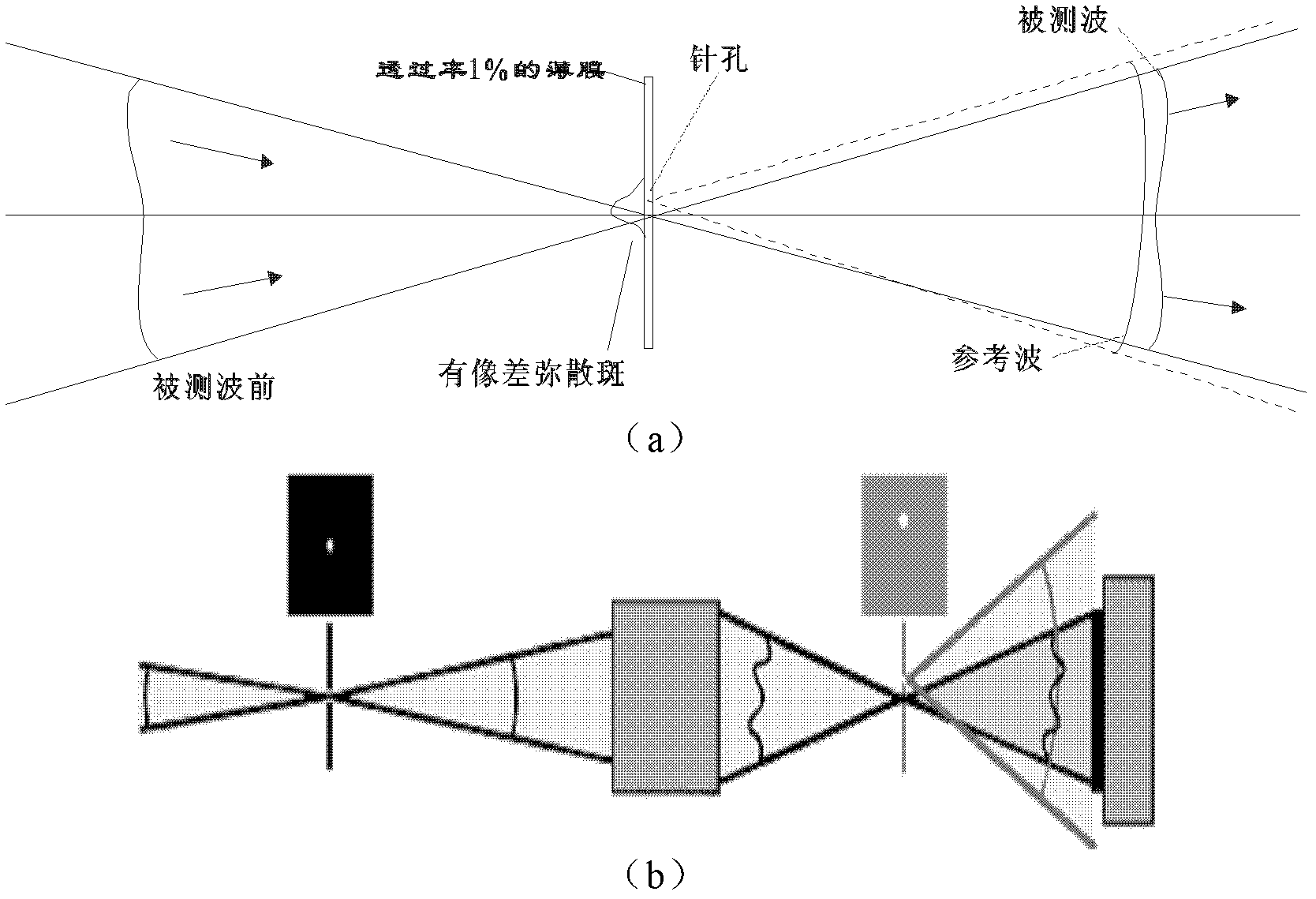
[0008] From the development and application principle of the point diffraction interferometer, it can be seen that the point diffraction interferometer uses the principle of small holes to produce ideal diffraction spherical waves for measurement. In practical applications, the processing of small holes has become a difficult problem. Whether it is electron beam processing, For atomic beam processing, ion beam processing and other processing technologies, it is difficult to process ideal small holes with nanometer precision, and it is difficult to achieve perfect roundness and smoothness of small holes.

Method used


Image

  • Detection device and method for small hole calibration
  • Detection device and method for small hole calibration
  • Detection device and method for small hole calibration

Examples


Embodiment Construction

[0046] In order to make the object, technical solution and advantages of the present invention clearer, the present invention will be described in further detail below in conjunction with specific embodiments and with reference to the accompanying drawings.

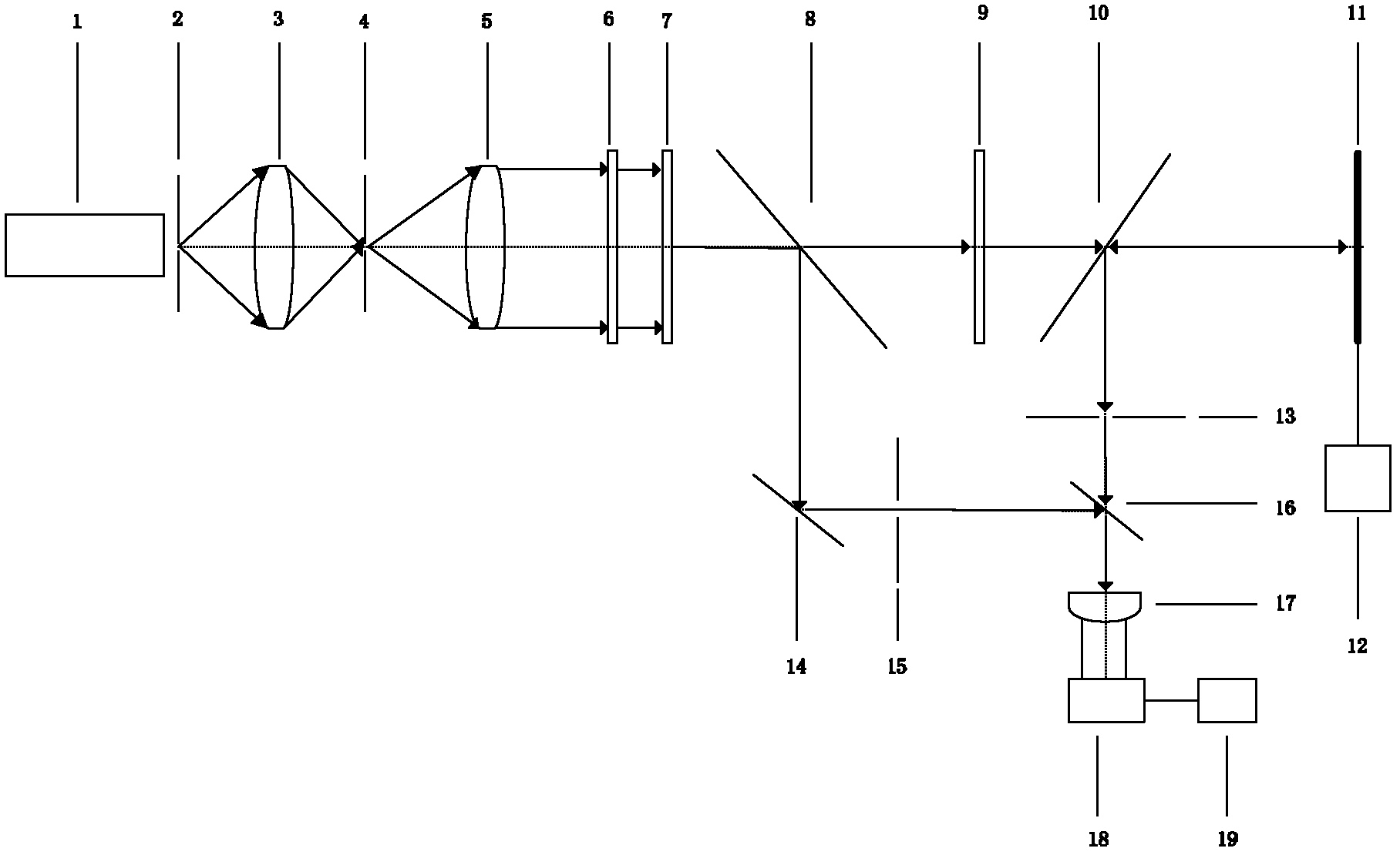
[0047] like figure 1 Represent the structural representation of the device of the present invention, by laser 1, filter hole 2, condenser mirror 3, spatial filter 4, beam expander mirror 5, λ / 2 wave plate 6, λ / 4 wave plate 7, half-transparent mirror 8, Attenuation sheet 9, beam splitter 10, first mirror 11, second mirror 14, phase shifter 12, first clamping frame 13, second clamping frame 15, beam splitter 16, converging optical unit 17, CCD Detector 18, computer 19. Among them: the filter hole 2 is placed at the light outlet of the laser 1, the condenser lens 3 is placed between the filter hole 2 and the spatial filter 4, the filter hole 2 is placed at the object plane position, and the spatial filter 4 is placed at th...


PUM


Abstract

The invention provides a detection device and method for small hole calibration, wherein light emitted by a laser is divided into two paths of light after passing through a filter hole, a condenser lens, a spatial filter, a beam expanding lens, a lambda / 2 wave plate, a lambda / 4 wave plate and a semi-transmitting semi-reflecting mirror; the first path of light is reflected by a reflector after passing through an attenuation plate and a beam splitter, and the reflected light is further reflected by the beam splitter to a first small hole so that diffracted spherical wave is produced by the first small hole and then is transmitted through the beam splitter; the second path of light passing through the semi-transmitting semi-reflecting mirror is reflected by the reflector to irradiate a second small hole; the diffracted spherical wave produced by the second small hole is reflected by the beam splitter before forming interference with the diffracted spherical wave produced by the first small hole; interference fringes pass through the condenser lens and then are collected by an optical detector; and finally, the errors of the diffracted spherical waves produced by three small holes areobtained through predetermined replacement operations. The detection device and the detection method provided in the invention are capable of improving the measurement accuracy of a point-diffractioninterferometer and reducing the processing cost of a high-accuracy small hole.

Description

technical field [0001] The invention belongs to the technical field of optical detection, in particular to a detection device and method for small hole calibration. Background technique [0002] High-precision interferometric surface measurements are becoming more and more important, not only in the traditional field of optical manufacturing, but also in new fields such as the surface of optical discs or the surface of semiconductor crystals. There are more and more requirements for the detection accuracy of pv value in the sub-nanometer range. With the rapid development of modern industry and science and technology, especially the continuous improvement of modern large-scale integrated circuit technology, the requirements for system precision are increasing day by day. In lithography systems, ever-shorter wavelength requirements require us to use higher precision lithography objectives. Before that, we need higher precision detection technology to meet the needs of proces...

Claims


Application Information

Patent Timeline
IPC IPC(8): G01J9/02
Inventor 贾辛许嘉俊邢廷文
Owner INST OF OPTICS & ELECTRONICS - CHINESE ACAD OF SCI
Learn More