Power module and method for manufacturing same

A technology of a power module and a manufacturing method, which is applied in the manufacturing of semiconductor/solid-state devices, electrical components, and electric solid-state devices, etc., can solve the problems of reduced joint reliability, reduced joint reliability, and increased operating temperature, and can prevent reliability. Deterioration, thermal stress suppression, and quality improvement effects

Inactive Publication Date: 2012-05-09
MITSUBISHI ELECTRIC CORP
View PDF6 Cites 5 Cited by
  • Summary
  • Abstract
  • Description
  • Claims
  • Application Information

AI Technical Summary

Problems solved by technology

[0006] However, there is a problem that the heat of the power element is transferred to the joint portion of the aluminum wire that is joined to the power element, causing the temperature to rise and the reliability of the junction to decrease.
In addition, due to the difference between the thermal expansion coefficient (linear expansion coefficient) of the power element and the thermal expansion coefficient (linear expansion coefficient) of the aluminum wire, thermal stress is repeatedly applied, and there is a problem that fatigue damage or fracture may occur near the interface
In particular, if it is a device that can operate at high temperature such as a SiC device, the operating temperature will be further increased, and the reliability of the junction will be significantly reduced.

Method used


Image

  • Power module and method for manufacturing same
  • Power module and method for manufacturing same
  • Power module and method for manufacturing same

Examples


Embodiment approach 1

[0024]

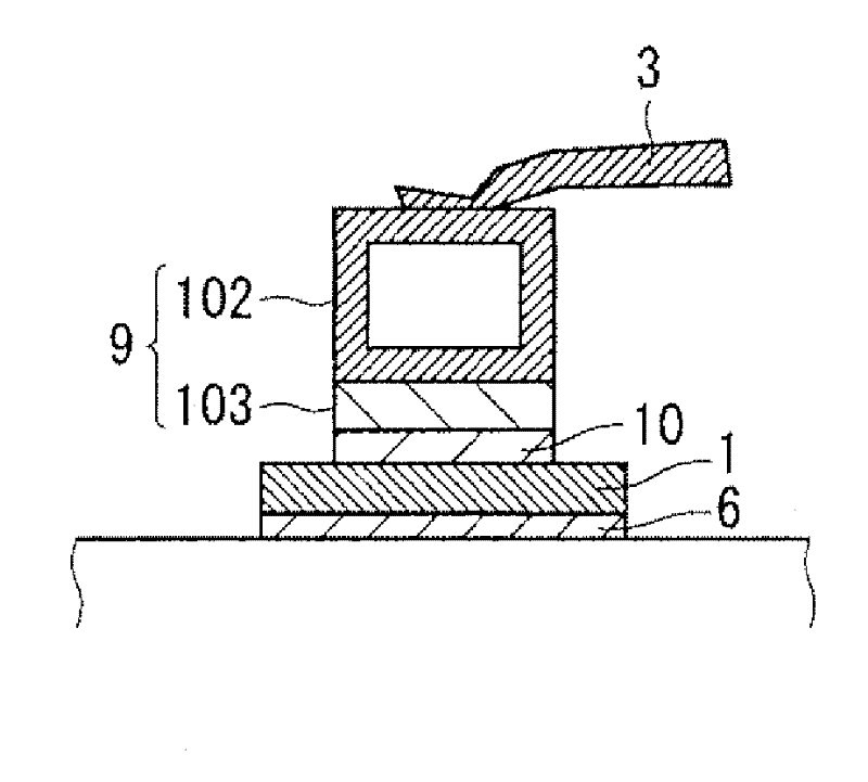
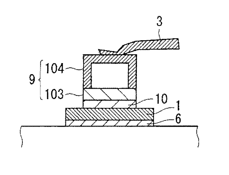
[0025] The power module according to Embodiment 1 of the present invention will be described using the drawings. Such as figure 1 As shown, the power module of the present invention is provided in the box body 8 with: a bottom plate 7; an insulating substrate 5 is arranged on the bottom plate 7 through the solder 6; a power element 1 is arranged on the insulating substrate 5 through the solder 6; The wiring member 9 as the first wiring member is bonded to the surface electrode of the power element 1 via the bonding material 10; the terminal 4 is connected to the wiring member 9 via the aluminum wire 3 as wiring; and the sealing material 2 is filled in the case 8 And covers insulating substrate 5 , power element 1 , wiring member 9 , and aluminum wire 3 . By using SiC or the like, which is a wideband gap semiconductor, as the power element 1 , a device capable of operating at a higher temperature can be realized.

[0026] The wiring member 9 is made of a highly con...

Embodiment approach 2

[0038]

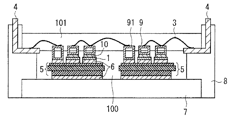
[0039] Figure 4 A power module according to Embodiment 2 is shown. As shown in the figure, in addition to the configuration of the power module shown in Embodiment 1, the power module further includes a wiring member 91 having a first side surface bonded to the insulating substrate 5 as a second wiring member. The rectangular cylindrical metal on the surface pattern connects the wiring member 91 and the terminal 4 via the aluminum wire 3 .

[0040] Here, the sealing material 2 can also be filled in the case body 8 as in the first embodiment, but in the second embodiment, the aluminum wire 3 is used on the side surface (the second side surface) where the wiring member 9 and the wiring member 91 are joined. ) is filled with a sealing material 100 (first sealing material) such as epoxy resin and cured so that at least it is exposed, and then the aluminum wire 3 is bonded to the exposed surfaces of the wiring members 9 and 91 . After that, the remaining exposed porti...

Embodiment approach 3

[0049]

[0050] Figure 5 A power module in the case of using a plurality of power elements connected in parallel in Embodiment 3 is shown. As shown in the figure, in addition to the configuration of the power module shown in Embodiment 2, the power module of Embodiment 3 further includes a wiring member 90, and the wiring members provided corresponding to each power element 1 are arranged on the second side surface side. joined to each other.

[0051] The wiring member 90 is an integral structure straddling a plurality of power elements 1 . With this structure, the intensity of ultrasonic vibrations to withstand the weight applied at the time of joining the aluminum wire 3 is further increased compared to Embodiment 2, and the surface area for heat dissipation is also increased due to the formation of the connection portion. Therefore, a further heat dissipation effect can be expected.

[0052]

[0053] According to Embodiment 3 of the present invention, in the power m...


PUM


Abstract

Provided is a power module that prevents a deterioration of reliability of bonded portions of aluminum wires, and enables a high-temperature operation of a Si or SiC device. A power module according to the present invention includes: insulating substrates (5) arranged in a case (8); power elements (1) bonded on the insulating substrates (5); wiring members (9) as first wiring members which are rectangular tube-like metal, and have first side surfaces bonded to surface electrodes of the power elements (1); aluminum wires (3) as wires connected to second side surfaces of the wiring members (9), which are opposite to the first side surfaces, and a sealing material (2) filled into the case (8) while covering the insulating substrates (5), the power elements (1), the wiring members (9) and the aluminum wires (3).

Description

technical field [0001] The invention relates to a power module and a manufacturing method thereof, in particular to a power module working at high temperature and a manufacturing method thereof. Background technique [0002] In existing power modules, usually, the insulating substrate is made of aluminum nitride (hereinafter AlN), aluminum oxide (Al 2 o 3 ), silicon nitride (Si 3 N 4 ) and other ceramics, with copper or aluminum metal patterns formed on the surface and back. The power element arranged on the insulating substrate is bonded to the metal pattern of the insulating substrate by soldering, and the wiring from the electrode of the power element to the terminal part is carried out with aluminum wires, and the whole is sealed with a sealing material such as silicone gel. seal. This is the case shown in Patent Document 1. [0003] patent documents [0004] Patent Document 1: Japanese Patent Application Laid-Open No. 6-5742. [0005] When the power module is wo...

Claims


Application Information

Patent Timeline
Patent Type & Authority Applications(China)
IPC IPC(8): H01L23/00H01L23/488H01L23/29H01L21/50
CPCH01L2224/85205H01L2224/45124H01L2224/48699H01L2924/01019H01L2924/01029H01L2924/0132H01L2224/48472H01L2224/48091H01L2224/45014H01L2924/014H01L2924/01013H01L24/49H01L2224/45147H01L2224/32225H01L24/48H01L24/85H01L23/3121H01L24/45H01L2924/10272H01L23/3135H01L24/33H01L2924/01047H01L2224/48137H01L24/32H01L2924/19107H01L25/0655H01L23/24H01L2224/33181H01L2224/48491H01L2924/01005H01L2924/01033H01L2924/01006H01L25/072H01L2924/10253H01L2924/01014H01L2224/73265H01L2224/48139H01L2224/49H01L24/73H01L2924/351H01L2924/181H01L2224/48227H01L2224/05639H01L2224/05647H01L2924/00014H01L2224/40137H01L24/40H01L2924/00012H01L2924/00H01L2924/3512H01L2924/00015H01L2924/206H01L2224/73221H01L23/48H01L23/28
Inventor 筱原利彰
Owner MITSUBISHI ELECTRIC CORP
Why Eureka
Try Eureka