Supercharge Your Innovation With Domain-Expert AI Agents!

Light source device

A light source device and light wave technology, which is applied in the direction of light source, electric light source, point light source, etc., can solve the problems of complex core adjustment process, achieve the effect of reducing the configuration interval, reducing the number of parts, and saving space

Inactive Publication Date: 2012-05-09
CITIZEN WATCH CO LTD
View PDF14 Cites 9 Cited by
  • Summary
  • Abstract
  • Description
  • Claims
  • Application Information

AI Technical Summary

Problems solved by technology

[0017] As mentioned above, the multiplexer of the spatial optical system using the dichroic prism and the cross prism has the following problems: It requires three-dimensional calibration for each RGB light-emitting element, and the alignment process for this calibration is complicated

Method used


Image

  • Light source device
  • Light source device
  • Light source device

Examples


Embodiment

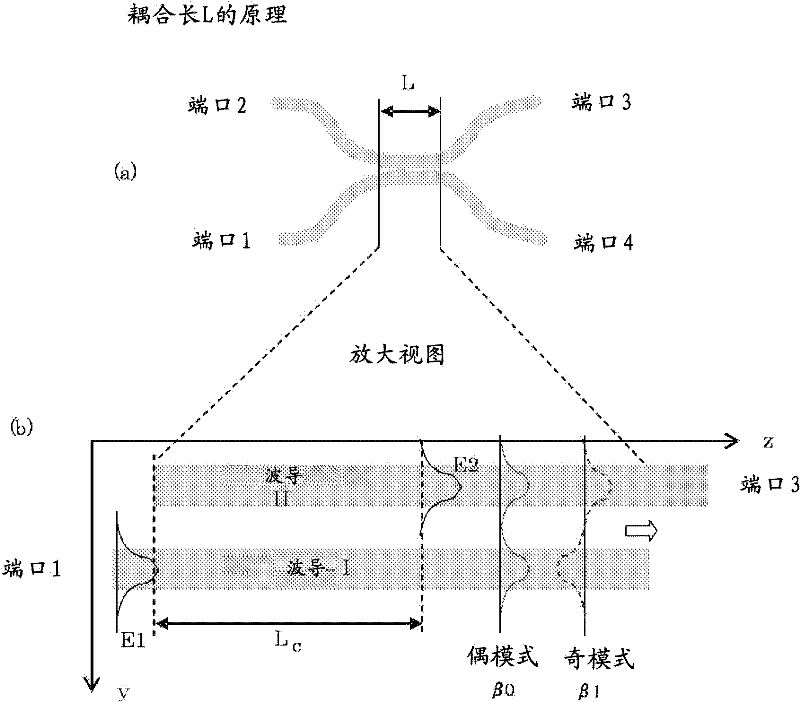
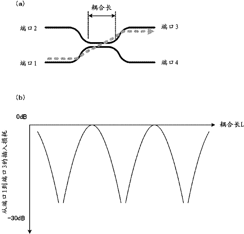
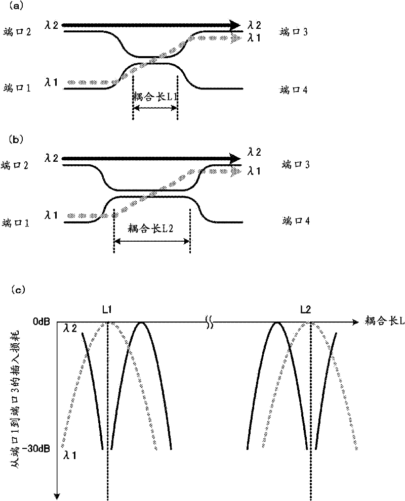
[0242] Next, use Figure 17 ~ Figure 64 , illustrating an embodiment of the multi-wavelength multiplexer and light source device of the present invention.

[0243] First, use Figure 17 ~ Figure 23 , illustrating an embodiment of the multi-wavelength multiplexer of the present invention. in addition, Figure 17 , 18 The illustrated embodiment is a structural example in which light-emitting elements and emission terminals are arranged on two sides of a quadrangular semiconductor substrate opposite to each other, Figure 19 ~ Figure 23 This is an example of a structure in which a light emitting element and an emission terminal are arranged on two sides perpendicular to each other of a quadrangular semiconductor substrate.

[0244] exist Figure 17 In the light source device 10A, the optical element substrate 8 forming the module of the waveguide and the multi-wavelength multiplexer 1, and the modules of the laser elements 4 (4a to 4c) are mounted on the wiring substrate 9 t...


PUM


Abstract

In a light source device for combining light waves with at least three wavelengths and outputting thus combined light waves, an optical system element and an electrical system element are formed on a semiconductor substrate, thereby eliminating the necessity of optical members such as an optical connector, and saving space to place the optical members as well as reducing arrangement spacing. In addition, the space necessary for wiring in an electrical circuit is reduced. Therefore, an integration degree of each of the elements, the optical system element and the electrical system element, is enhanced. The optical system element and the electrical system element are formed in layers on the same conductor substrate, thereby reducing the area that is required in configuring a parallel establishment of the optical system element and the electrical system element.

Description

technical field [0001] The present invention relates to, for example, a light source device suitable for a small projector. Background technique [0002] In a projector that displays color images by projecting light in the R wavelength region, G wavelength region, and B wavelength region on a screen, it is necessary to project the light in each wavelength region to one point in order to form a color image. As a configuration for projecting light in each wavelength range to one point, a technique is known in which light in each wavelength range is scanned by a mirror mechanism using a MEMS (Micro Electro Mechanical System). [0003] This structure has the following problems: when the light of each wavelength region integrated in the horizontal direction is scanned by the mirror, the timing of projecting the light of each wavelength region is shifted, and the scanning angle range of each wavelength region is different. [0004] Patent Document 1 is known as a prior art for so...

Claims


Application Information

Patent Timeline
IPC IPC(8): G02B6/42F21S2/00G02B6/122F21Y101/02
CPCG02B6/4215G02B6/12007G02B6/12004
Inventor 井出昌史泷泽亨
Owner CITIZEN WATCH CO LTD
Features
  • R&D
  • Intellectual Property
  • Life Sciences
  • Materials
  • Tech Scout
  • Unparalleled Data Quality
  • Higher Quality Content
  • 60% Fewer Hallucinations
Learn More