
Side hanging type double-power supply drive rail electric bus

A dual-power, side-mounted technology, used in tram tracks, rails, motor vehicles, etc., can solve the problems of unsatisfactory actual results, neglecting the other, affecting the smooth flow of vehicles, etc., to achieve low energy consumption, low cost, comfort and safety. The effect of bus service

Inactive Publication Date: 2012-05-23
盐城海旭数控装备有限公司
View PDF5 Cites 13 Cited by
  • Summary
  • Abstract
  • Description
  • Claims
  • Application Information

AI Technical Summary

Problems solved by technology

However, this kind of scheme mainly relies on strong administrative management. Judging from the demonstration situation, the actual effect is not satisfactory. A three-dimensional express bus scheme is proposed. The body spans two lanes and has two floors. Cars less than 2 meters high can pass through its "legs", and the upper space is used to carry passengers.
Governments around the world are constantly exploring and improving the current public transportation system, hoping to study a form of public transportation with high quality, high efficiency, low energy consumption, low pollution, and low cost, so as to relieve urban traffic pressure and reduce vehicle pollutant emissions. Although some progress has been made, there are still technical difficulties that have not been overcome in practical application.

Method used


Image

  • Side hanging type double-power supply drive rail electric bus
  • Side hanging type double-power supply drive rail electric bus
  • Side hanging type double-power supply drive rail electric bus

Examples


Embodiment Construction

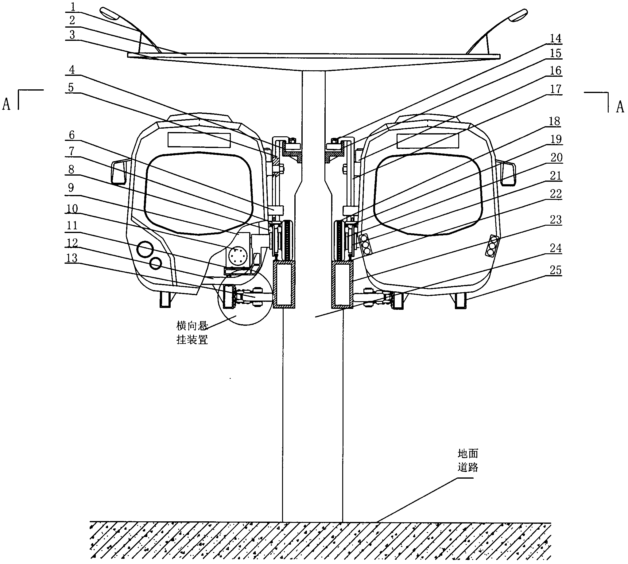
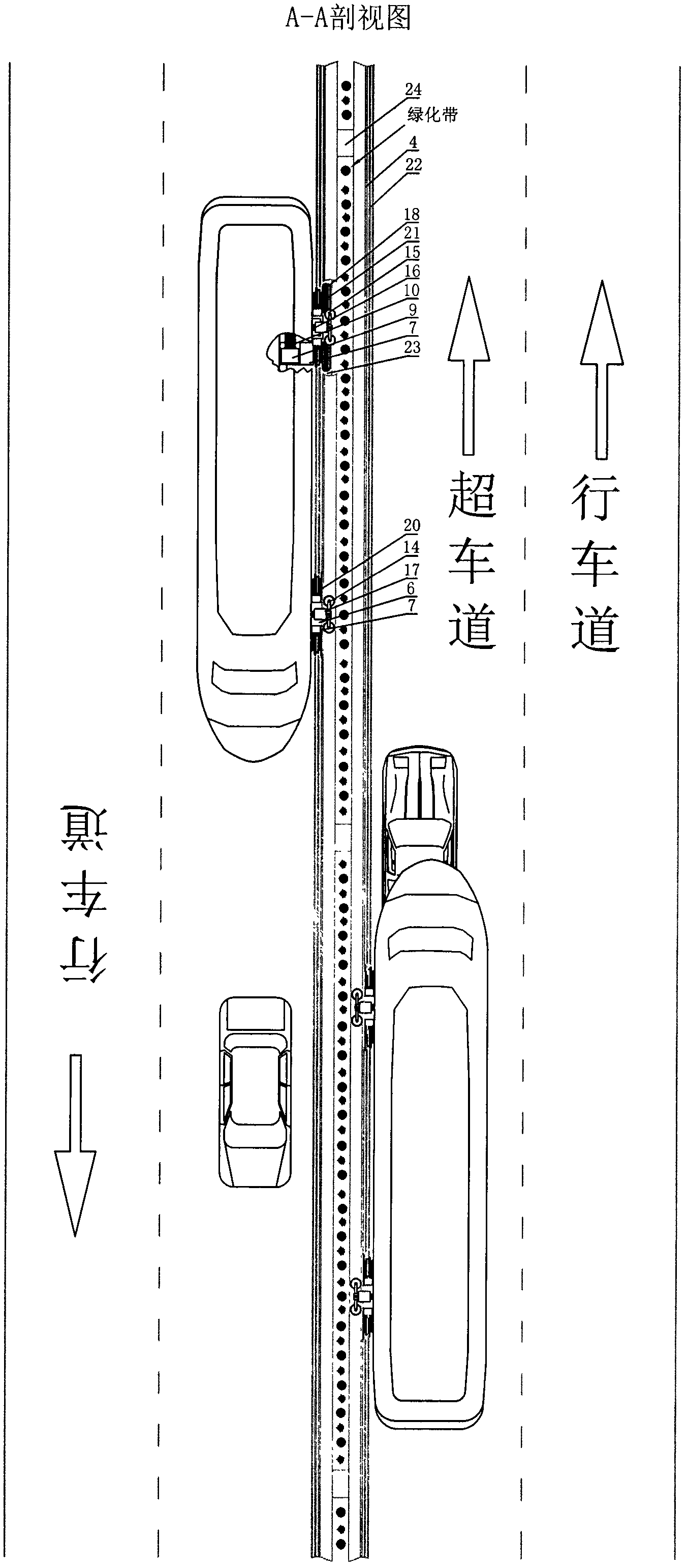
[0017] exist figure 1 , 2 , 3, 4, 5, 6, 7, and 8, the elevated girder piers 24 are narrow at the top and wide at the bottom, and are constructed separately in the center of the road. The two sides of the elevated girder piers 24 are 2.8-3.5 meters away from the ground, respectively embedded with monorails, It is the lower track 23, a guide rail 22 is respectively provided on the outer side of the top of the lower track 23, and an upper track 4 is arranged on both sides of the narrow part of the upper part of the elevated beam pier 24, forming a The top of the elevated beam pier 24 is provided with a crossbeam 3, the crossbeam 3 is connected with the solar panel 2, the solar panel 2 is laid along the extending direction of the elevated beam pier 24, and the two sides of the top of the solar panel 2 are provided with solar lamps 1. The upper part of the solar cell panel 2 is provided with a power grid, and the carriage is suspended on the rails on both sides of the elevated be...


PUM


Abstract

The invention relates to a side hanging type double-power supply drive rail electric bus which belongs to a novel bus. The side hanging type double-power supply drive rail electric bus comprises a solar lamp, a solar cell panel, a beam, an upper rail, a connecting shaft, a safety hoop, a vibration damping bracket, a vibration damper, a reduction gearbox, a motor, a motor bracket, a keel, a lower lateral wheel, wheel arms, an upper lateral wheel, a hinge, a suspension column, typres, an air spring, a support beam, a guide wheel, a guide rail, a lower rail, overhead girder piers, a bus axle, a bearing seat, a stable shaft and a safety shaft. The electric bus is provided with a novel platform and is configured with a special vehicle rotating device by adopting a modern bus technology and matching with intelligent traffic and operation management. The overhead girder piers are constructed in the center of a road in rows, the rails are vertically expanded at both sides of the overhead girder piers, vehicles are driven in opposite direction on the rails, the vehicles at the bottom are driven without obstruction, and thereby, the efficient space multiplexing on the traditional road is realized; by adopting new energy drive, the zero emission is realized; and the electric bus has the advantages of safety, environmental protection, rapidness and fashion and is the electric bus with high quality, high efficiency, low energy consumption, low cost and zero emission.

Description

technical field [0001] The invention relates to a new type of bus, in particular to a side-mounted rail car driven by dual power supplies. Background technique [0002] Since the reform and opening up, the national economy has grown rapidly, and "scientific and technological innovation, independent innovation" has become the mainstream of domestic industrial development. Various fields and national life are gradually developing in the direction of intensive, energy-saving, emission-reducing, and low-carbon. The Chinese government promises to the world that the emission reduction strategy will be an important implementation measure of the national policy, and energy conservation and environmental protection, new energy, and new energy vehicles will be listed as national strategic emerging industries, aiming to achieve sustainable development through energy conservation, emission reduction, and innovation. and solve the climate problem faced by all mankind. With the continuo...

Claims


Application Information

Patent Timeline
IPC IPC(8): B61B9/00B61B12/02B61B12/04E01D19/00E01B25/22
CPCY02T30/40Y02T30/00
Inventor 徐文锦凌锦荣陈新施中昕徐鹏杰王根亮李金权蔡留春卞义忠严立剑
Owner 盐城海旭数控装备有限公司
Learn More