Method for collecting floating oil on water surface

A technology for oil slicks and oil slicks on water surfaces, applied in separation methods, grease/oily substances/suspton removal devices, liquid separation, etc., can solve the problems of low oil slick collection efficiency and unsuitable for large-scale oil slick collection, and achieve The effect of improving oil slick collection efficiency

Active Publication Date: 2012-05-23
北京仁创日升石油开采技术有限公司
View PDF6 Cites 21 Cited by
  • Summary
  • Abstract
  • Description
  • Claims
  • Application Information

AI Technical Summary

Problems solved by technology
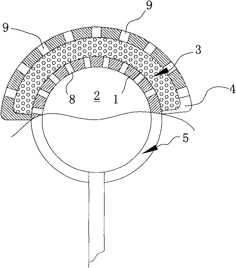
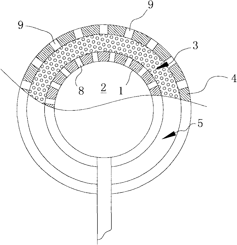
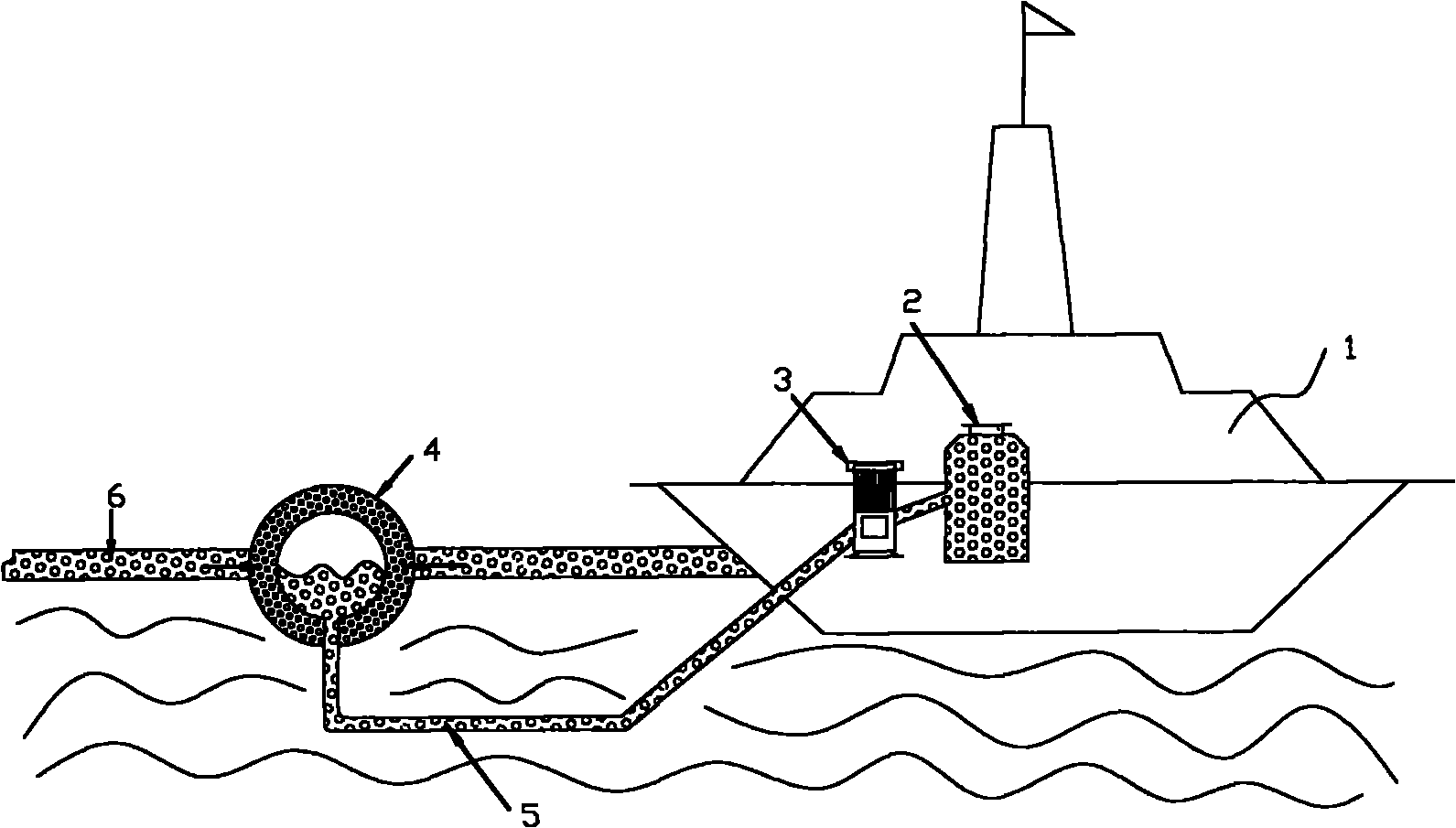
However, the oil slick collection efficiency of the method in the prior ar

Method used


Image

  • Method for collecting floating oil on water surface
  • Method for collecting floating oil on water surface
  • Method for collecting floating oil on water surface

Examples


Example Embodiment

[0071] Preparation of dearomatized petroleum ether: use column chromatography to combine 60-100 mesh coarse-pored microsphere silica gel and 70-120 mesh neutral chromatography alumina (activated at 150-160°C for 4 hours), and pack it before cooling completely Into a glass column with an inner diameter of 25mm and a height of 750mm. The lower layer of silica gel is 600mm high and covered with 50mm thick alumina. Commercially available petroleum ether (60-90°C fraction) is passed through this column to remove aromatics. Collect petroleum ether in a narrow-necked bottle, use water as a reference at 225nm on the UV spectrophotometer, and measure the treated petroleum ether so that its transmittance should not be less than 80%.

[0072] Standard curve drawing

[0073] To 7 50mL volumetric flasks, add 0, 2.00, 4.00, 8.00, 12.00, 20.00 and 25.00mL of standard oil use solution, and dilute to the mark with petroleum ether (60-90℃). On an ultraviolet spectrophotometer, at 254nm, use a 1 cm...

Example

[0078] Preparation Example 1

[0079] This example is used to illustrate the preparation of coated silica sand coated with a lipophilic and hydrophobic film on the surface provided by the present invention.

[0080] Heat 3kg of quartz sand particles (with a density of 1.65 g / cm3) with an average particle diameter of 0.4mm to 250°C and put them in a sand mixer to stir, then cool to 200°C and add polyamide resin modified epoxy resin 0.15kg, fully stir to make the resin evenly distributed on the outer surface of the quartz sand particles, then add aliphatic amine curing agent (the weight ratio of the curing agent to the resin is 2:100) to solidify, and finally cool to room temperature and break to obtain a film Silica sand (with a coating thickness of 1-2 microns). The sphericity of the obtained coated silica sand is 0.72, and the particle diameter distribution is 320-450 microns.

Example

[0081] Preparation Example 2

[0082] This example is used to illustrate the preparation of coated silica sand coated with a lipophilic and hydrophobic film on the surface provided by the present invention.

[0083] The coated particles were prepared according to the same method as Preparation Example 1, except that the phthalate plasticizer was added before adding the curing agent, and the weight ratio of the phthalate plasticizer to the resin was 10:100, and the mixture was fully stirred to obtain The coating thickness of the coated silica sand is 2-3 microns, the sphericity is 0.75, and the particle diameter distribution is 350-430 microns.


PUM

PropertyMeasurementUnit
Diameteraaaaaaaaaa
Thicknessaaaaaaaaaa
Diameteraaaaaaaaaa

Abstract

The invention provides a method for collecting floating oil on a water surface. In the method, an oil-water separation device is provided, wherein the device comprises an oil collecting cavity (2) defined by a wall (1), at least partial surface of the wall (1) is covered with a porous oleophylic hydrophobic layer (3), the part of the wall (1), covered with the porous oleophylic hydrophobic layer (3), allows water and oil to pass through, the device also comprises a fixing layer (4) which is covered on the surface or above the porous oleophylic hydrophobic layer (3) and is used for limiting the flowing of the porous oleophylic hydrophobic layer, and the fixing layer (4) allows the water and the oil to pass through, the hole diameter of the porous oleophylic hydrophobic layer (3) is 300 to 850mu, and the porosity is 10 to 40%; the oil-water separation device is placed on the water surface with the floating oil such that the at least partial surface of the fixing layer (4), which is covered on the surface or above the porous oleophylic hydrophobic layer (3) and is used for limiting the flowing of the porous oleophylic hydrophobic layer, is in contact with the water surface with the floating oil; and then the floating oil in the oil collecting cavity is collected. By means of the method provided by the invention, a large area of floating oil on the sea can be effectively collectedand the efficiency of collecting the floating oil is remarkably improved.

Description

technical field [0001] The invention relates to a method for collecting floating oil on the water surface. Background technique [0002] The world's oil mainly relies on sea transportation, and oil tankers running aground, colliding, running aground, and destroying the structure of the hull itself will cause serious oil spill accidents. At the same time, more and more offshore drilling platforms and offshore oil pipelines have been built one after another, and there are also hidden dangers to the environment or their own structures, which will lead to offshore oil spills and large-scale floating on the sea. Therefore, by means of effective sea oil slick recovery methods, relying on advanced sea surface oil slick recovery devices can minimize its negative impact. [0003] The existing oil slick collection device can play the role of collecting and treating the oil slick on water with small area and less liquid volume, but it is not suitable for dealing with a large amount of...

Claims


Application Information

Patent Timeline
IPC IPC(8): C02F1/40
Inventor 秦升益
Owner 北京仁创日升石油开采技术有限公司
Why Eureka
Try Eureka