High-temperature vapor-water mixed jet cleaning system and method

A high-temperature water vapor and cleaning system technology, which is applied in cleaning methods and tools, chemical instruments and methods, cleaning methods using liquids, etc., can solve the problems of underlying silicon loss, damage to the sensitive structure of the wafer surface, etc., and achieve deglue efficiency Enhanced, loss-minimized, residue-free effect

Inactive Publication Date: 2012-05-30
INST OF MICROELECTRONICS CHINESE ACAD OF SCI
View PDF6 Cites 3 Cited by
  • Summary
  • Abstract
  • Description
  • Claims
  • Application Information

AI Technical Summary

Problems solved by technology

For the removal of implanted photoresist on silicon, alkaline or acidic fluorine-based solutions can be used, but it will cause loss of the underlying silicon; plasma removal technology can also be used, but the charge generated by the non-uniform plasma will damage the crystal. Sensitive structures on round surfaces

Method used


Image

  • High-temperature vapor-water mixed jet cleaning system and method
  • High-temperature vapor-water mixed jet cleaning system and method

Examples


Embodiment 1

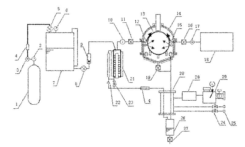
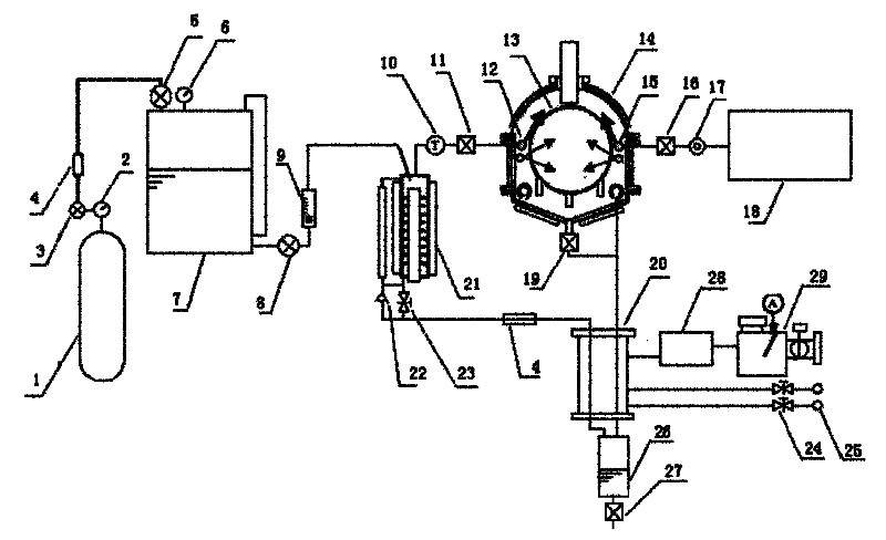
[0028] The process of the cleaning method is as follows: put the sample into the tray 13 and fix it; heat the heat exchanger 21 by setting the temperature value of the constant temperature control and display device 10, and when the temperature reaches the required temperature, adjust the pressure reducing valve 3 and open the valve 5 and valve 8, adjust the flow meter 9, at this time N 2 Through the valve 5 and the valve 8, and through the flow meter 9 to control the flow rate, the deionized water is sent into the heat exchanger 21, and the deionized water absorbs heat in the heat exchanger 21 to form a high-temperature steam of 200 ° C, and then passes through the nozzle 12 Spray to the sample surface fixed on the tray 13 in the cleaning chamber 14; adjust the mass flow controller 17, open the valve 16, and the ozone produced by the ozone generator 18 is sprayed to the sample surface fixed on the tray 13 through the nozzle 15; The sample surface fixed on the tray 13 in the c...

Embodiment 2

[0030] The process of the cleaning method is as follows: put the sample into the tray 13 and fix it; heat the heat exchanger 21 by setting the temperature value of the constant temperature control and display device 10, and when the temperature reaches the required temperature, adjust the pressure reducing valve 3 and open the valve 5 and valve 8, adjust the flow meter 9, at this time N 2 Through the valve 5 and the valve 8, and through the flow meter 9 to control the flow, the deionized water is sent into the heat exchanger 21, and the deionized water absorbs heat in the heat exchanger 21 to form a high-temperature steam of 300 ° C, and then passes through the nozzle 12 Spray to the sample surface fixed on the tray 13 in the cleaning chamber 14; adjust the mass flow controller 17, open the valve 16, and the ozone produced by the ozone generator 18 is sprayed to the sample surface fixed on the tray 13 through the nozzle 15; The sample surface fixed on the tray 13 in the chambe...

Embodiment 3

[0032] The process of the cleaning method is as follows: put the sample into the tray 13 and fix it; heat the heat exchanger 21 by setting the temperature value of the constant temperature control and display device 10, and when the temperature reaches the required temperature, adjust the pressure reducing valve 3 and open the valve 5 and valve 8, adjust the flow meter 9, at this time N 2 Through the valve 5 and the valve 8, and through the flow meter 9 to control the flow, the deionized water is sent into the heat exchanger 21, and the deionized water absorbs heat in the heat exchanger 21 to form a high-temperature steam of 400 ° C, and then passes through the nozzle 12 Spray to the sample surface fixed on the tray 13 in the cleaning chamber 14; adjust the mass flow controller 17, open the valve 16, and the ozone produced by the ozone generator 18 is sprayed to the sample surface fixed on the tray 13 through the nozzle 15; The sample surface fixed on the tray 13 in the chambe...


PUM


Abstract

The invention discloses a cleaning system, which comprises an ozone generator, a deionized water storage tank, a control device, two nozzles and a cleaning chamber, wherein the control device is used for heating deionized water to a high temperature state; the outlet of the deionized water storage tank is connected with the nozzle inlet of one of the two nozzles through the control device; the outlet of the ozone generator is connected with the other nozzle inlet; and the outlets of the two nozzles are connected with the two inlets of the cleaning chamber respectively. The invention further discloses a cleaning method, which comprises the following steps of: forming vapor in a high-temperature state; jetting vapor and ozone to the cleaning chamber simultaneously; and cleaning a sample sheet with a mixed fluid consisting of high-temperature vapor and ozone. According to the cleaning system and the method disclosed by the invention, a thick inorganic carbonized layer, a bottom organic photoresist and cured and cross-linked SU-8 can be stripped fully, degumming efficiency is greatly increased, residues are eliminated, and the loss of a substrate material is minimized.

Description

technical field [0001] The invention relates to the technical field of semiconductors, in particular to a high-temperature water vapor and ozone mixed jet cleaning system and method. Background technique [0002] In modern CMOS devices, almost all substrate structures are formed via ion implantation. The energetic ions can damage the photoresist, making it difficult to remove. After implantation, these ions may exist as oxide layers, sub-oxide layers, or organic compounds. These energetic ions also transform the photoresist surface into a carbonaceous layer of diamond-type and graphite-type mixtures. The carbonization process therefore makes removal of implanted photoresist challenging. For the removal of implanted photoresist on silicon, alkaline or acidic fluorine-based solutions can be used, but it will cause loss of the underlying silicon; plasma removal technology can also be used, but the charge generated by the non-uniform plasma will damage the crystal. Sensitive...

Claims


Application Information

Patent Timeline
Patent Type & Authority Applications(China)
IPC IPC(8): B08B3/02B08B13/00
Inventor 王磊景玉鹏
Owner INST OF MICROELECTRONICS CHINESE ACAD OF SCI
Why Eureka
Try Eureka