

Millimeter wave frequency source device
A millimeter-wave frequency band and millimeter-wave technology, applied in the field of millimeter-wave frequency source devices, can solve problems such as poor stability of millimeter-wave frequency, achieve the effect of improving stability and avoiding interconnection problems
- Summary
- Abstract
- Description
- Claims
- Application Information
AI Technical Summary
Problems solved by technology
Method used
Image

Examples
Embodiment 1
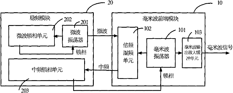
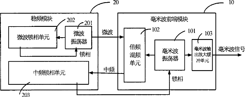
[0022] figure 1 It is a schematic diagram of a millimeter wave frequency source device according to an embodiment of the present invention. Such as figure 1 As shown, the millimeter wave frequency source device of this embodiment includes a millimeter wave front-end module 10 and a frequency stabilization module 20 . Among them: the millimeter wave front-end module 10 is used to generate the oscillation signal of the millimeter wave frequency band; after the oscillation signal of the millimeter wave frequency band is multiplied, it is mixed with a microwave signal generated by the frequency stabilization unit to obtain an intermediate frequency signal, and the intermediate frequency signal is transmitted To the frequency stabilization module; receive a phase-locking signal from the frequency stabilization module, and perform phase-locking on the oscillation signal of the millimeter-wave frequency band generated by the millimeter-wave front-end module according to the phase-lo...
Embodiment 2
[0027] This embodiment will further describe the millimeter wave frequency source device on the basis of the first embodiment.
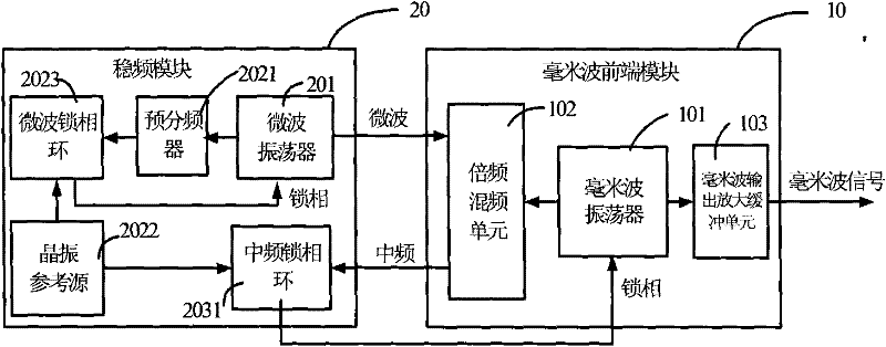
[0028] figure 2 It is a schematic diagram of a second millimeter-wave frequency source device according to an embodiment of the present invention. Such as figure 2 As shown, overall, the millimeter-wave frequency source device proposed in this embodiment includes two modules: a millimeter-wave front-end module 10 and a frequency stabilization module 20, wherein the millimeter-wave front-end module 10 includes at least one frequency-doubling mixing unit 102 , a millimeter wave oscillator 101 , usually also includes a millimeter wave output amplification unit 103 . The frequency stabilization module 20 includes a crystal oscillator reference source 2022 , a microwave phase-locked loop 2023 , a microwave oscillator 201 , an intermediate frequency phase-locked loop 2031 , and a prescaler 2021 .
[0029] The working principle of the frequency source ...
Embodiment 3
[0032] This embodiment will describe the features of each component in Embodiments 1 and 2.
[0033]In this embodiment, the millimeter-wave front-end module 10 is a fully integrated millimeter-wave monolithic integrated circuit (MMIC) using monolithic integrated circuit technology, so that all millimeter-wave signals are transmitted in the single-chip circuit, that is, the millimeter-wave oscillator 101, the frequency multiplying and mixing unit 102 and the millimeter wave output amplification and buffering unit are integrated into the same chip. Preferably, the monolithic integrated circuit technology adopts the integrated circuit technology based on indium phosphide heterojunction bipolar transistor device (InP HBT), which has the characteristics of high device operating frequency and low flicker noise, and is suitable for millimeter wave frequency source application. In addition, the frequency multiplication and mixing unit 102 can be implemented directly by using a harmon...
PUM
 Abstract
Description
Claims
Application Information