Optical fiber sensing technology-based operating rod

An optical fiber sensing technology and joystick technology, which is applied in the field of joysticks based on optical fiber sensing technology, can solve problems such as limitations, and achieve the effects of low cost, good use effect, and easy processing and production

Inactive Publication Date: 2012-06-06
XIAN JINHE OPTICAL TECH
View PDF1 Cites 6 Cited by
  • Summary
  • Abstract
  • Description
  • Claims
  • Application Information

AI Technical Summary

Problems solved by technology

Of course, such a joystick cannot satisfy people's needs, so the joystick technology is also constantly developing, and there are various types such as capacitive, inductive, electromagnetic, and photoelectric. Chinese patent application number 200710000210.0 "magnetic field Inductive Joystick" discloses a joystick based on magnetic induction. Although the structure is exquisite and practical, it is similar to other joysticks and still transmits information based on the transmission form of electrical signals. This will cause problems in strong electromagnetic interference or strong radiation environments. Subject to greater interference, such as in nuclear power plants, power plants, substations and other places, the use is restricted

Method used


Image

  • Optical fiber sensing technology-based operating rod
  • Optical fiber sensing technology-based operating rod
  • Optical fiber sensing technology-based operating rod

Examples


Embodiment 1

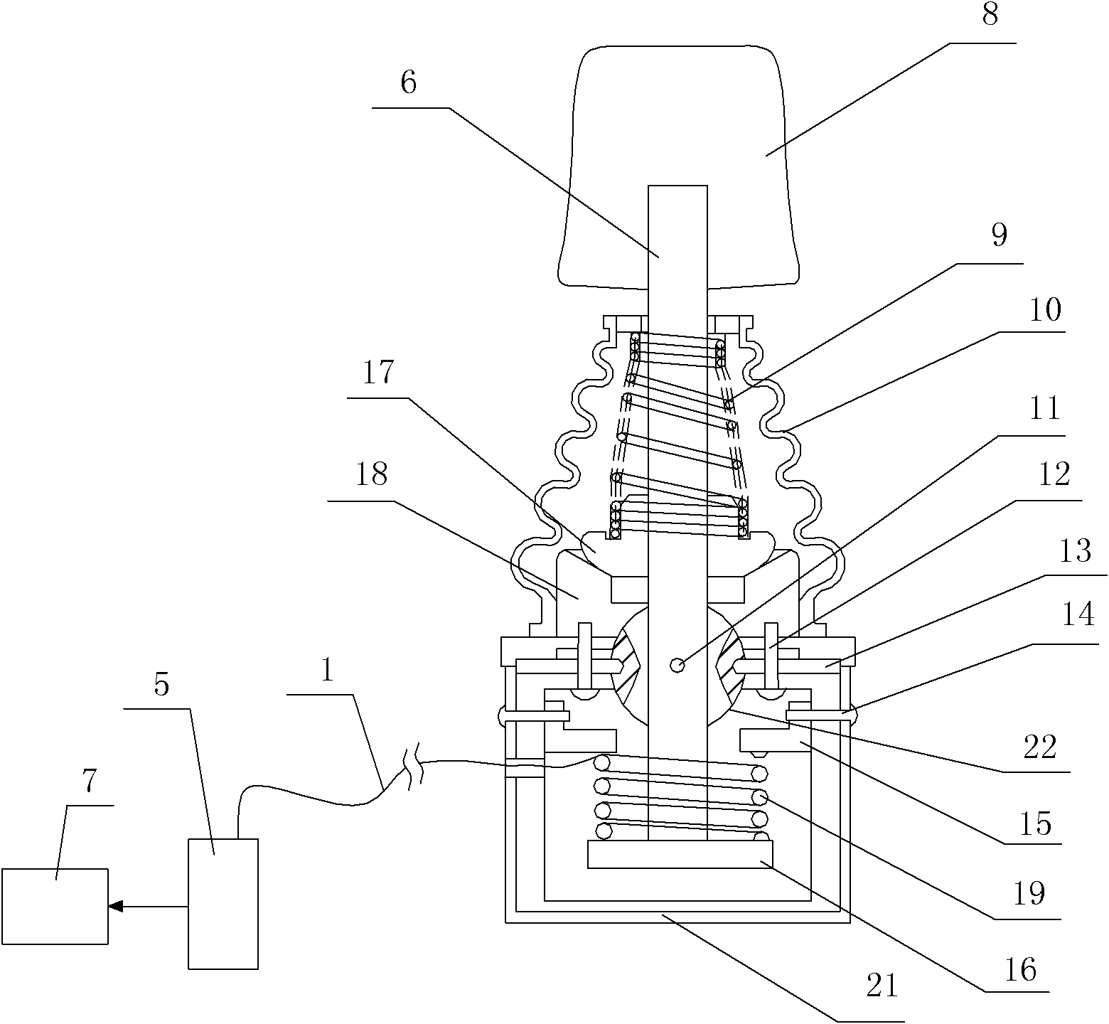
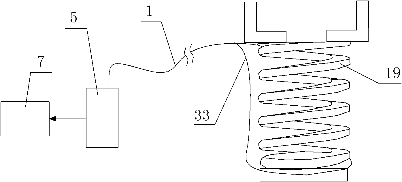
[0040] Such as figure 1 , figure 2 , image 3 and Figure 4 The shown joystick based on optical fiber sensing technology includes a joystick body 6, a base 18, a rotating shaft 22, a spring one 9 and a spring base 17, and the spring one 9 is sleeved on the joystick body 6, so The joystick body 6 is provided with a handle 8, and the spring base 17 is arranged under the spring one 9 to carry the spring one 9. The preferred method is that the spring one 9 is covered with a dust cover 10; The seat 18 is located below the spring base 17, the rotating shaft 22 is arranged on the base 18, and the rotating shaft 22 is arranged on the described base 18 through the first positioning pin 11 and the second positioning pin 13, preferably The method is that the first locating pin 11 and the second locating pin 13 are fixed on the base 18 by screws 12, the rotating shaft 22 is provided with an opening communicating up and down, and the joystick body 6 can extend out from the opening of t...

Embodiment 2

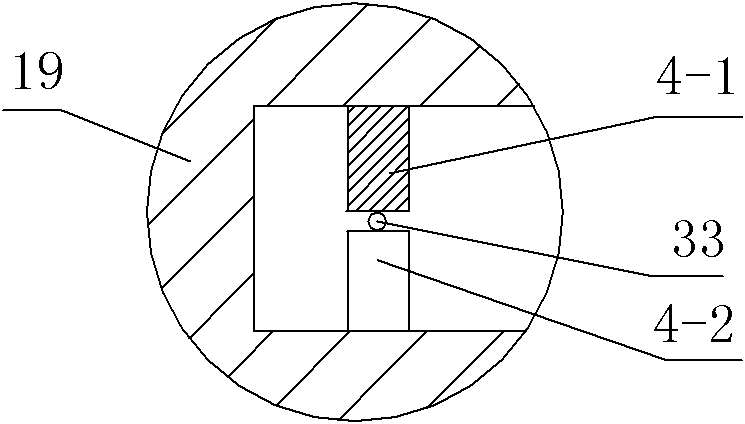
[0046] Such as Figure 5 , Figure 6 As shown, in this embodiment, the difference from Embodiment 1 is that the curved support is a spring 2 38, and the first A-side deformed tooth 4-1 and the first B-side deformed tooth 4-2 are correspondingly arranged on the spring 2 38, between two adjacent coils of spring wire, and the first A-side deformed teeth 4-1 and the first B-side deformed teeth 4-2 are alternately arranged. The preferred method is that the second A side deformation teeth 4-3 and the second B side deformation teeth 4-4 are also arranged on the spring two 38, and the second A side deformation teeth 4-3 and the second B side deformation teeth 4-4 4 are arranged alternately, and the second signal optical fiber 35 is clamped between the deformation teeth on both sides of the second A and B sides. The second A side deformation teeth 4-3 and the second B side deformation teeth 4-4 are along the spring Every 360 degrees of the curved support formed by two 38 is a cycle, ...

Embodiment 3

[0048] Such as Figure 7 , Figure 8 As shown, in this embodiment, the difference from Embodiment 1 is that the curved support is a bellows 40, and the first A-side deformation teeth 4-1 and the first B-side deformation teeth 4-2 are correspondingly arranged on the bellows On the two opposite sides of the recess on the pipe wall 42 of 40, the first A-side deforming teeth 4-1 and the first B-side deforming teeth 4-2 are alternately arranged. The preferred method is that the second A-side deformation teeth 4-3 and the second B-side deformation teeth 4-4 are also arranged on the pipe wall 42, and the second A-side deformation teeth 4-3 and the second B-side deformation teeth 4- 4 are arranged alternately, and the second signal optical fiber 35 is clamped between the deformation teeth on both sides of the second A and B sides, and the second deformation teeth 4-3 on the A side and the second deformation teeth 4-4 on the B side are along the Every 360 degrees of the tube 40 is a ...


PUM


Abstract

The invention discloses an optical fiber sensing technology-based operating rod, which comprises an operating rod main body, a base, a rotating shaft, a spring A and a spring base, wherein the spring A is sleeved on the operating rod main body, the spring base is arranged below the spring A, the base is arranged below the spring base, the rotating shaft is arranged on the base, the rotating shaft is provided with an opening which passes through the rotating shaft vertically, the operating rod main body can extend out from the opening of the rotating shaft, an extent end of the operating rod main body is provided with a movable plate, a shell is arranged below the base, the movable plate is arranged inside the shell, a fixed plate is fixed on the inner wall of the shell, and a curved bracket is arranged between the fixed plate and the movable plate; a plurality of first A-side deformation teeth and a plurality of first B-side deformation teeth are distributed on the curved bracket, and a curved passage for a first signal optical fiber to pass through is formed between the head parts of every adjacent first A-side deformation tooth and the first B-side deformation tooth; and the first signal optical fiber is connected with a test unit, and the test unit is connected with a processing unit. The optical fiber sensing technology-based operating rod has a simple structure and reasonable design, is convenient to process and produce and has low cost.

Description

technical field [0001] The invention relates to a joystick, in particular to a joystick based on optical fiber sensing technology. Background technique [0002] The basic principle of the joystick is to convert the movement of the rocker controlled by the hand into electronic information that the computer can process. Joysticks are used in a variety of mechanical devices, including modern jet fighters, excavators, industrial controls, remote and radio controls, radar and navigation systems, robots and manipulators, measurement systems, medical devices and wheelchairs, to name a few. The different joystick technologies differ primarily in how much information they transmit. [0003] The simplest joystick is the one found in early microcomputer game consoles, which is nothing more than a special electronic switch. Its basic structure consists of a joystick resting on a plastic base with a resilient rubber casing. There is a circuit board in the base just below the joystick....

Claims


Application Information

Patent Timeline
Patent Type & Authority Applications(China)
IPC IPC(8): G05G1/04
Inventor 杜兵
Owner XIAN JINHE OPTICAL TECH
Why Eureka
Try Eureka