Eureka AIR delivers breakthrough ideas for toughest innovation challenges, trusted by R&D personnel around the world.

Three-channel slurry fuel gasification burner

A fuel gasification, three-channel technology, applied in the direction of granular/powdered fuel gasification, combined combustion mitigation, etc., can solve the problems of burner head abrasion acceleration, impact on service life, low speed, etc., to improve carbon conversion rate , avoid direct erosion, and the overall structure is simple

Active Publication Date: 2012-06-13
SHANGHAI BOILER WORKS
View PDF6 Cites 18 Cited by
  • Summary
  • Abstract
  • Description
  • Claims
  • Application Information

AI Technical Summary

Problems solved by technology

When the design of the burner head is unreasonable, it may cause the abrasion of the wall material of the burner head and affect its service life
Existing patented technologies such as U.S. Patents 4736693, 4858538, 4443228 and Chinese Patent 89104265 all use a burner with a straight tube structure as the central nozzle. The common disadvantage is that the material lacks an acceleration process before it is injected into the reactor. The speed is low, the atomization effect is not good, and it is easy to ablate the burner
U.S. patents 3,743,606, 3,705,108, and 4,443,230 adopt the structure of the front end of the central tube to increase the flow rate, and the flow rate at the outlet of the central nozzle is increased to enhance the atomization effect of the burner, but the increase in speed will accelerate the abrasion of the burner head. Affected the service life of the nozzle
And for a single-nozzle top-mounted gasifier, excessive flow rate of the material at the outlet of the top nozzle will directly affect the residence time of the material in the gasifier, thereby affecting the overall carbon conversion rate
US patent 6228224 adopts a four-channel burner structure to improve the atomization effect of the burner, but this will make the burner structure more complex and increase the difficulty of processing and maintenance
In addition, most of the patents mentioned above do not use high-temperature resistant and anti-wear coatings to protect the burner end surface material on the burner section. Since the temperature near the nozzle hole of the burner is as high as 1400°C and above, although cooling water is used to cool the end surface, it is difficult to avoid The emergence of severe working conditions such as ablation and wear of the nozzle head

Method used


Image

  • Three-channel slurry fuel gasification burner
  • Three-channel slurry fuel gasification burner
  • Three-channel slurry fuel gasification burner

Examples


Embodiment 1

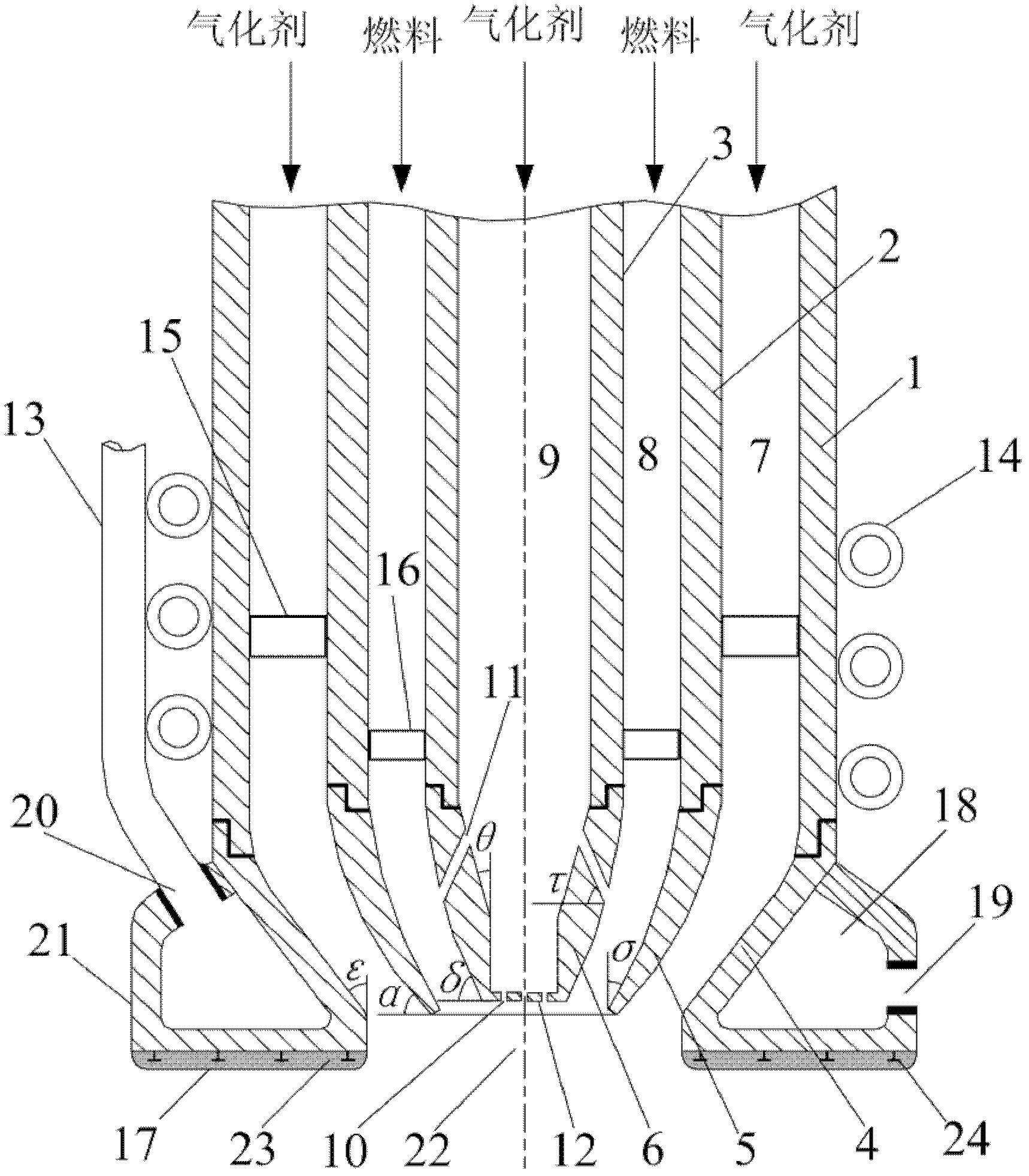
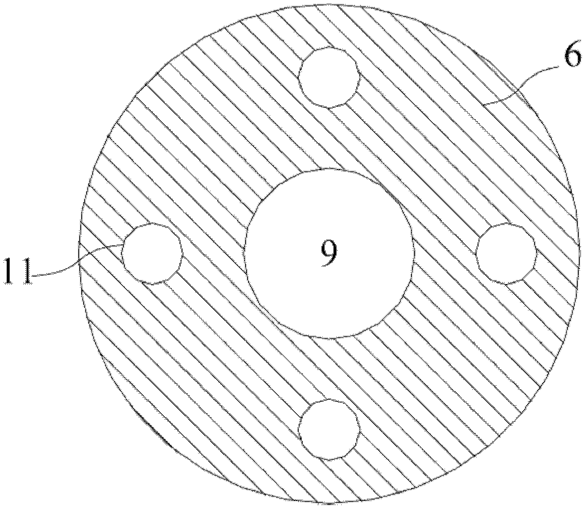
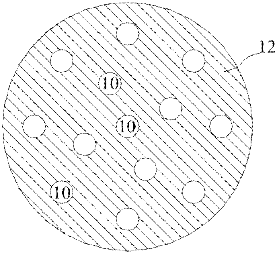
[0025] If a certain 2000t / d single-nozzle top-mounted coal-water slurry gasifier is taken as an example, the inner contraction half-angle θ of the center nozzle 6 of the gasification burner according to the present invention is 30°, and its lateral inclination angle δ is 60°. The side gasification agent spray holes 11 of 6 are 1 layer, 6 holes in total, the angle τ between the spray hole direction and the horizontal plane is 75°, and the spray hole diameter is 5mm; the outlet end face 12 has 7 holes, and the spray hole diameter is 5mm.

[0026] The inner contraction half angle σ of the ring nozzle 5 in the gasification burner is 30°, and the outer inclination angle α is 60°. The inner contraction half angle ε of the outer ring nozzle 4 is 45°.

[0027] The distance between the central nozzle 6 of the gasification burner and the outlet end face of the middle ring nozzle 5 is 25 mm. The outlet end face distance between the middle ring nozzle 5 and the outer ring nozzle 4 is 10m...


PUM


Abstract

The invention discloses a three-channel slurry fuel gasification burner, which comprises an outer ring channel jet pipe, a middle ring channel jet pipe, a center channel jet pipe, an outer ring nozzle, a middle ring nozzle and a center nozzle that are coaxial. A slurry fuel enters a gasification furnace from a middle ring channel, and a gasification agent enters the gasification furnace from a center channel and an outer ring channel in two parts. The lateral sides of the center nozzle are provided with a lateral gasification agent jet orifice, along which the gasification agent can enter a middle ring channel from the center channel. The end face of the center nozzle is provided with an end face gasification agent jet orifice. At the center nozzle, the gasification agent is divided into a plurality of material flows, which are respectively jetted from the lateral gasification agent jet orifice and the end face gasification agent jet orifice of the center nozzle. The gasification agent jetted from the lateral gasification agent jet orifice contacts with the slurry fuel of the middle ring channel inside the head of the burner. And the slurry fuel also mixes with the gasification agent of the center channel and the outer ring channel at the outlet area of the burner, thus achieving a good atomization effect.

Description

technical field [0001] The invention relates to a slurry fuel atomization device, in particular to a three-channel slurry fuel gasification burner. Background technique [0002] The clean and efficient utilization of coal and other carbon-containing fuels has gradually become an important issue in today's energy utilization. Fuel gasification to syngas can provide leading technologies for modern chemical production, combined cycle power generation (IGCC power generation for short), indirect coal liquefaction, and coal-to-hydrogen systems. At present, the gasification technology of coal and other carbon-containing fuels to produce syngas is generally divided into two categories, one is slurry gasification technology, and the other is dry powder solid gasification technology. Currently, slurry gasification technology is the most widely used at home and abroad. gasification technology. As one of the key components of gasification, the development of burner technology directly...

Claims


Application Information

Patent Timeline
IPC IPC(8): C10J3/50
CPCY02E20/18
Inventor 倪建军李月华乌晓江熊杰
Owner SHANGHAI BOILER WORKS
Why Eureka
Eureka Blog
Learn More