Gas well-drilling erosion experiment method

A technology of gas drilling and experimental method, applied in the direction of drilling with liquid/gas jet, etc., can solve the problems such as the inability to meet the requirements of the gas drilling annulus return velocity, the low erosion rate, and the failure of the jar

Inactive Publication Date: 2012-06-13
SOUTHWEST PETROLEUM UNIV
View PDF5 Cites 24 Cited by
  • Summary
  • Abstract
  • Description
  • Claims
  • Application Information

AI Technical Summary

Problems solved by technology

Under the joint action of the above factors, it will inevitably lead to the failure of drilling tools and pipes during gas drilling, and serious erosion of ground equipment (such as compressors, valves) and pipelines
For example, the field statistics of gas drilling in Northeast Sichuan show that the erosion failure of gas drilling tools is far more serious than that of conventional drilling fluid drilling, and the life of drilling tools during gas drilling is only 1/3~1/5 of that of conventional drilling fluid drilling; In Iran’s TABNAK gas field, due to high-density oxygen, corrosion of formatio

Method used


Image

  • Gas well-drilling erosion experiment method
  • Gas well-drilling erosion experiment method
  • Gas well-drilling erosion experiment method

Examples


Embodiment 1

[0023] Embodiment 1 Air foam fluid erosion test method

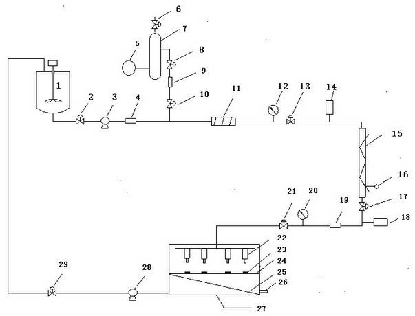
[0024] A stable foam with a certain mass concentration is pre-prepared in the base liquid tank 1. The formula of the foam base liquid is: 0.6% K12 (the main component is sodium lauryl sulfate) + 0.2XC (biopolymer) + 0.2% HV-CMC ( high viscosity carboxymethyl cellulose) + tap water. The foam base liquid enters the porous foam generator 11 from the shut-off valve 2, the centrifugal pump 3, and the flow meter 4, and the air enters the porous foam through the air compressor 5, the air storage tank 7, the shut-off valve 8, the flow meter 9, and the shut-off valve 10 Generator 11. Adjust the gas flow rate to 0.5m 3 / min, the liquid flow rate is 8.6L / min, and the gas-liquid ratio is 58.1. Continuously add quartz sand with a particle size of 20-80 mesh from the sand adding device 14 in an amount of 80 g / min, and the sand-containing foam is heated through the cable heating pipe 15, and the foam temperature measured by the ther...

Embodiment 2

[0027] Embodiment 2 pure air erosion test method

[0028] The air enters the sand adding device 14 from the air compressor 5, the air storage tank 7, the shut-off valve 8, the flow meter 9, the shut-off valve 10, the pressure gauge 12, and the shut-off valve 13, and the air flow rate is adjusted to 0.4m 3 / min, continuously add quartz sand with a particle size of 20-80 mesh from the sand adding device 14 in an amount of 60g / min, the sand-containing air is heated through the cable heating tube 15, and the air temperature measured by the thermocouple thermometer 16 is 50°C, and the pressure gauge The reading of 20 is 1.8MPa.

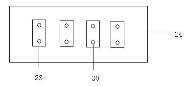
[0029] The high-temperature, high-pressure sand-containing air flowing out from the stop valve 21 enters the erosion chamber 27 . Four erosion nozzles 22 with an inner diameter of 2 mm are installed on the upper part of the erosion chamber 27, and the sand-containing air ejected through the erosion nozzles 22 scours the metal hanging piece 23 on the metal...

Embodiment 3

[0030] Example 3 Test method for erosion of brine drilling fluid filled with air

[0031] Pre-prepared a certain volume of brine drilling fluid in the base fluid tank 1, the basic formula of brine drilling fluid: 4% bentonite + 5% NaCl + 0.2% HPAM (anionic polyacrylamide) + 0.3% MMH (positive gel) + 0.5% SJ-2 (one-way plugging agent) + 0.8% SMP (fluid loss reducer) + tap water. The brine drilling fluid enters the pipeline through the stop valve 2, the centrifugal pump 3 and the flow meter 4 to mix with the air. Adjust the gas flow rate to 0.15m 3 / min, the liquid flow rate is 6.7L / min, and the gas-liquid ratio is 22.4 at this time. Continuously add quartz sand with a particle size of 20-80 mesh from the sand adding device 14 at a rate of 50 g / min. The sand-containing drilling fluid is heated through the cable heat tracing tube 15. The temperature of the drilling fluid measured by the thermocouple thermometer 16 is 50 ° C, and the pressure at the outlet end is Table 20 reads ...


PUM

PropertyMeasurementUnit
The inside diameter ofaaaaaaaaaa

Abstract

The invention relates to a gas well-drilling erosion experiment method for the field of oil and gas well-drilling, which comprises the following steps: 1 first providing erosion media (including gas, atomizing liquid, foam or aerated mud) through an erosion medium supply system; 2 warming the erosion media through a heating system (the temperature can rise to 120 DEG C), and achieving the goal of imitating a high-temperature environment in a well; 3 monitoring erosion medium parameters (such as foam quality, half-life period, temperature, pressure and density) in real time through a sampler; and 4 finishing an erosion experiment by adjusting a dimension of a nozzle in an erosion system and inclined amplitude of a metal baffle. The gas well-drilling erosion experiment method can provide erosion experiments for imitating various gas well-drilling media, the goal of imitating a high-temperature high-pressure environment in the well can be achieved by temperature and pressure monitoring, fluid erosion speed can be changed by replacing nozzles with different apertures, and an erosion angle can be changed by adjusting inclined amplitude of the metal baffle.

Description

technical field [0001] The invention relates to a gas drilling erosion test method used in the field of oil and gas drilling. Background technique [0002] At present, according to the different circulating media, gas drilling can be divided into pure gas drilling (air, nitrogen, natural gas, carbon dioxide, flue gas, diesel engine exhaust, etc.), atomization drilling, foam drilling and aerated drilling. The circulating medium used in gas drilling itself inevitably has oxygen or carbon dioxide corrosion problems, and the return rate of cuttings in the annulus is higher than that of ordinary drilling. In addition, during the drilling process, formations with harsh geological conditions may be encountered (such as formations with strong abrasiveness, many water layers, rich in acidic gases, etc.). Under the joint action of the above factors, it will inevitably lead to the failure of drilling tool pipes in the process of gas drilling, and serious erosion of ground equipment (s...

Claims


Application Information

Patent Timeline
IPC IPC(8): E21B7/18
Inventor 万里平孟英峰李皋李永杰魏纳
Owner SOUTHWEST PETROLEUM UNIV
Why Eureka
Try Eureka