Coal powder combustion system used in high-moisture type coal oxygen-enriched combustion

A technology of oxygen-enriched combustion and pulverized coal combustion, which is applied to burners, burners, combustion methods and other directions of burning powder fuel, can solve the problems of large drying output, high water vapor content, low oxygen concentration, etc., and achieve pulverized coal deflagration. less likely effect

Active Publication Date: 2012-06-13
SHANGHAI BOILER WORKS
View PDF6 Cites 27 Cited by
  • Summary
  • Abstract
  • Description
  • Claims
  • Application Information

AI Technical Summary

Problems solved by technology

However, when flue gas is used to transport pulverized coal, the oxygen concentration in the transport medium is too low and the water vapor content is too

Method used


Image

  • Coal powder combustion system used in high-moisture type coal oxygen-enriched combustion
  • Coal powder combustion system used in high-moisture type coal oxygen-enriched combustion
  • Coal powder combustion system used in high-moisture type coal oxygen-enriched combustion

Examples


Embodiment 1

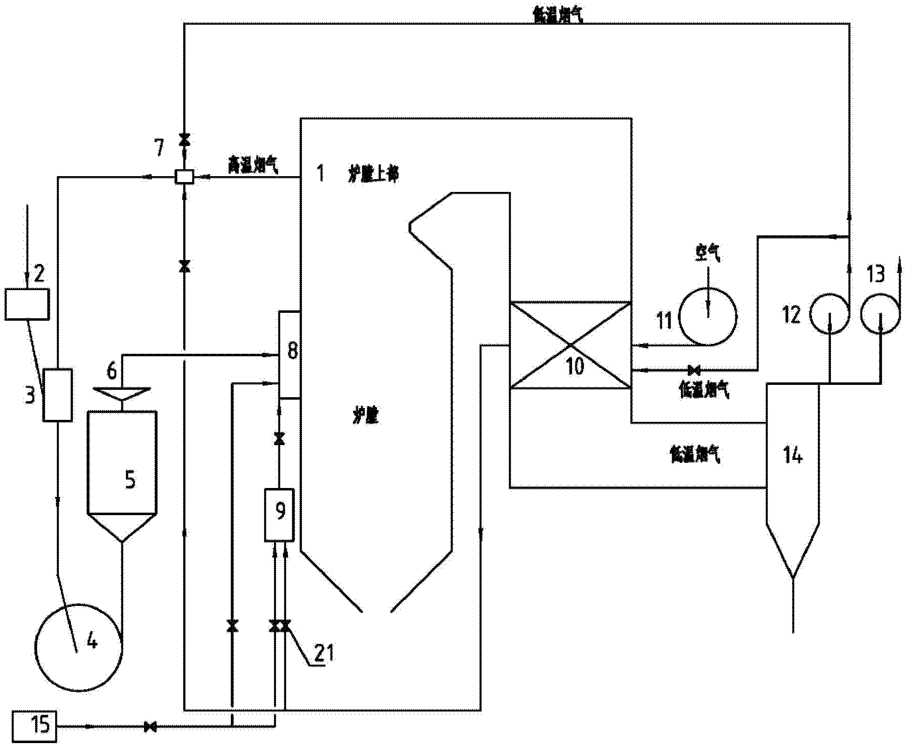
[0021] Below to figure 1 , image 3 Embodiments of the present invention will be described.

[0022] figure 1 It is an overall layout diagram of an embodiment of the oxyfuel combustion system. Such as figure 1 In the embodiment shown, the entire system includes a boiler body 1, a coal feeder 2, a descending drying pipe 3, a fan coal mill 4, a coarse powder separator 5, a pulverized coal distributor 6, a flue gas mixer 7, a burner 8, Secondary air box 9, air preheater 10, air blower 11, recirculation fan 12, induced draft fan 13, dust collector 14, oxygen making equipment 15, control valve 21.

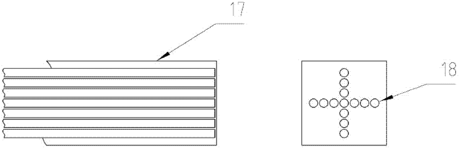
[0023] The primary air / powdered coal assembly in the burner 8 used in the combustion system is composed of two or more passages, of which the main passage passes through the pulverized coal and its conveying medium, and the other auxiliary passages pass hot air and oxygen-enriched air during air combustion. Take oxygen when burning. image 3 As an implementation form of the primar...

Embodiment 2

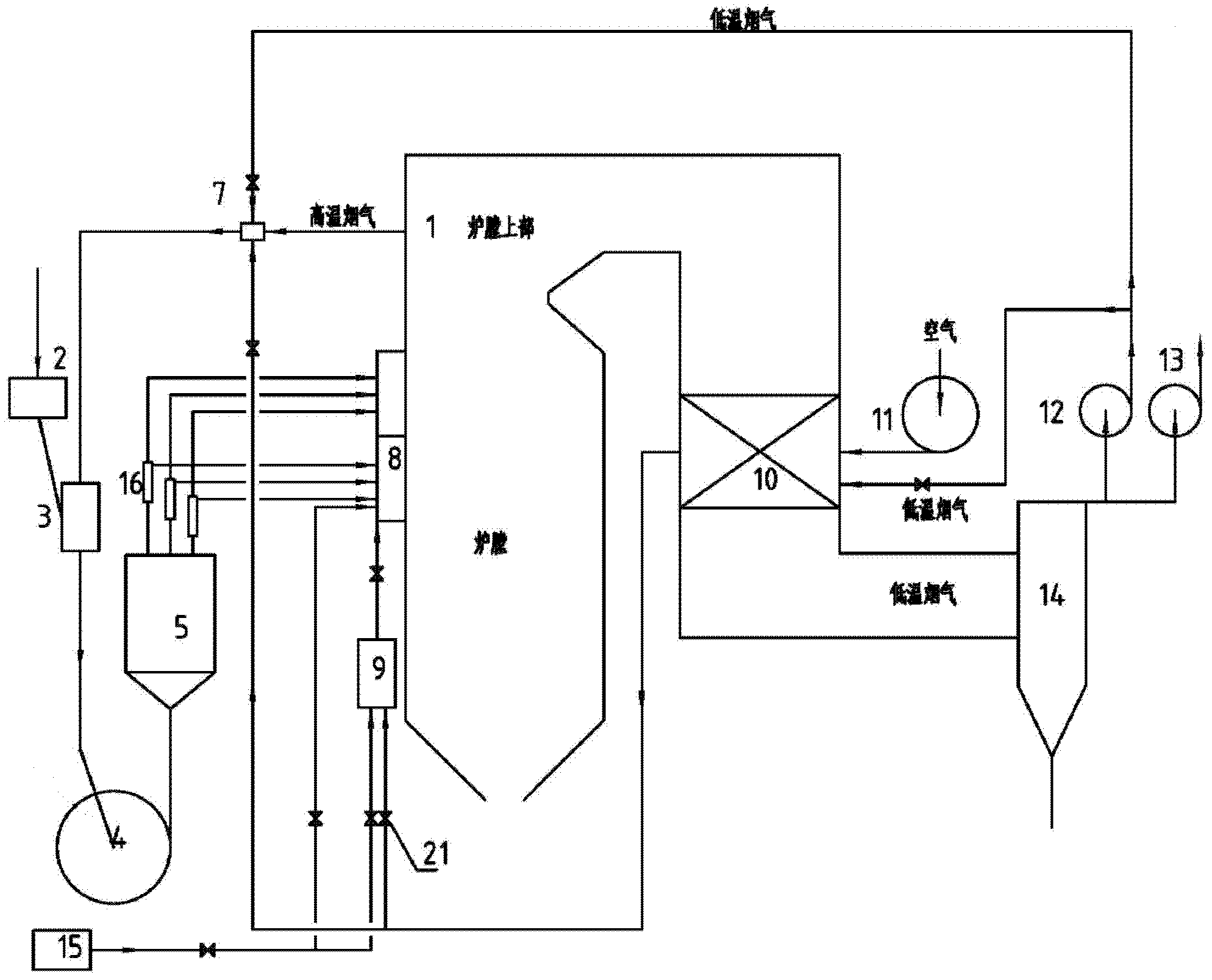
[0028] Below to figure 2 , image 3 Embodiments of the present invention will be described.

[0029] figure 2 It is an overall layout diagram of another embodiment of the oxyfuel combustion system. Such as figure 2In the embodiment shown, the entire system includes a boiler body 1, a coal feeder 2, a descending drying pipe 3, a fan coal mill 4, a coarse powder separator 5, a smoke-air mixer 7, a burner 8, a secondary air box 9, and an air Preheater 10, air blower 11, recirculation fan 12, induced draft fan 13, dust collector 14, oxygen making equipment 15, exhaust gas separator 16. In this system, the burner 8 is arranged in two layers, namely the lower main burner and the upper exhaust gas burner. The airflow at the outlet of the fan coal mill 4 can be separated by the exhaust air separator 16 . The outlet of the exhaust gas separator 16 is divided into two paths, one path means that a small part of the airflow and most of the pulverized coal can be separated and ent...


PUM


Abstract

The invention discloses a coal powder combustion system used in high-moisture type coal oxygen-enriched combustion. With the combustion system, a boiler can be switched between two modes, which are an air combustion mode and an oxygen-enriched combustion mode. According to the system, coal powder is prepared by using a fan coal-mill (4); a blower (11) is started, and the coal powder is delivered in a dry state by using a mixed gas of high-temperature flue gas, low-temperature flue gas and air, such that the combustion system is in an air combustion state. The blower (11) is stopped, and an oxygen producing apparatus (15) is started; the coal powder is delivered in a dry state by using a mixed gas of high-temperature flue gas and low-temperature flue gas, such that the combustion system is in an oxygen-enriched combustion state. Oxygen from the oxygen producing apparatus (15) is divided into two parts. One part is mixed with recycled low-temperature flue gas, and the mixed gas is delivered into a furnace as secondary gas flow. The other part with a form of pure oxygen is delivered into the furnace through a combusting apparatus. Therefore, oxygen for coal powder combustion can be supplemented.

Description

technical field [0001] The invention relates to a pulverized coal combustion system, in particular to a pulverized coal combustion system for oxygen-enriched combustion of high-moisture coal. Background technique [0002] Oxygen-enriched combustion technology as an important CO 2 Capturing technology is getting more and more attention. It can be used for technical transformation of existing boilers. In the oxygen-enriched combustion technology, pure oxygen and part of the recirculated flue gas are mixed and then enter the boiler for combustion, which can make the CO in the flue gas 2 Concentration of more than 80%, easy to capture. In order to make the temperature of the oxy-fuel combustion boiler close to that of air combustion, it is necessary to control the amount of recirculated flue gas so that the O entering the furnace 2 The concentration is maintained at a certain value. Numerous studies have shown that the O 2 The concentration value is about 25-35%. The reci...

Claims


Application Information

Patent Timeline
IPC IPC(8): F23C7/00F23D1/00F23L7/00
CPCY02E20/322Y02E20/32Y02E20/34
Inventor 肖琨张建文乌晓江陈楠
Owner SHANGHAI BOILER WORKS
Why Eureka
Try Eureka