
Position detection method of large-calibre millimetre wave/sub-millimetre wave telescope control system

A sub-millimeter wave and control system technology, applied in the direction of using feedback control, measuring devices, and electrical devices, can solve the problems of high cost, prolonged development cycle, and high development costs, achieving simple circuits, saving system costs, and Highly implementable effect

Inactive Publication Date: 2012-06-13
NANJING INST OF ASTRONOMICAL OPTICS & TECH NAT ASTRONOMICAL OBSE
View PDF4 Cites 14 Cited by
  • Summary
  • Abstract
  • Description
  • Claims
  • Application Information

AI Technical Summary

Problems solved by technology

The motors used in VLT and ALMA are produced by the Italian Fizz company and equipped with driving equipment, so the control system is much simplified, but the position signal is completed by the matching control card of HEIDENHAIN, and the cost is relatively high
[0004] For large astronomical telescopes, the biggest disadvantage of direct drive is that it needs to be customized, the development cost is high, and the development cycle is correspondingly lengthened.

Method used


Image

  • Position detection method of large-calibre millimetre wave/sub-millimetre wave telescope control system
  • Position detection method of large-calibre millimetre wave/sub-millimetre wave telescope control system
  • Position detection method of large-calibre millimetre wave/sub-millimetre wave telescope control system

Examples


Embodiment 1

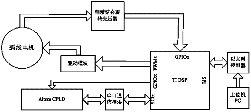
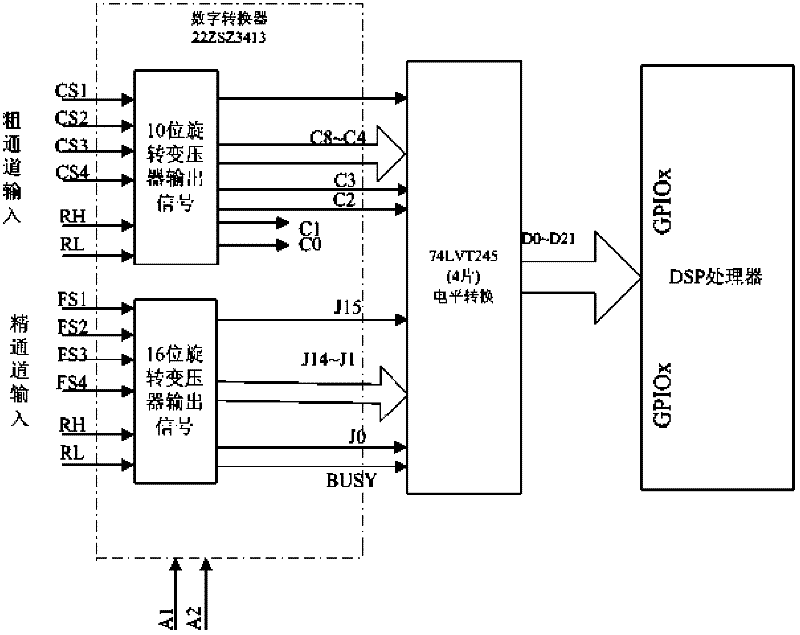
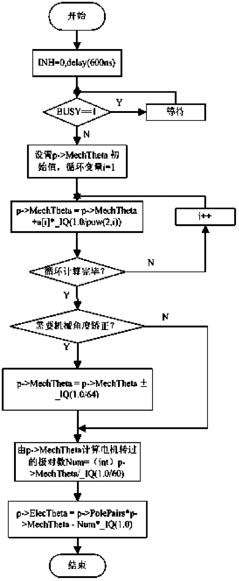
[0040] The technical solution for realizing the present invention is that the dual-channel multi-pole rotary transformer combined with coarse and fine is converted into a digital signal representing the absolute mechanical position signal through a digital converter, and then output to the parallel port of the DSP module after level conversion to calculate the absolute mechanical position. It is used as the position feedback signal of the position closed loop of the arc motor; it is converted into an electrical angle according to the characteristics of the arc motor, and is used to detect the electrical angle required for the vector control of the arc motor to form a current closed loop;

[0041] The Ethernet controller is used to realize communication between the DSP module and the upper computer PC, and the position given signal of the arc motor control system is given through the network interface;

[0042] The executive motor is an arc motor, which is a unit combination AC ...


PUM


Abstract

The invention relates to a position detection method of a large-calibre millimetre wave / sub-millimetre wave telescope control system, comprising the following steps that: (1), an upper computer sends an instruction to a DSP (Digital Signal Processor) module; (2), coarse and fine channels of a double-channel multi-polar rotary transformer output a signal through a digital converter, and, after being subjected to level conversion, the signals are transmitted to the DSP module; (3), the DSP module calculates an absolute mechanical position signal of an arc motor, so that the closed loop of the arc motor is realized; (4), the DSP module converts the signal into an electrical angle, so that the current closed loop of the arc motor in vector control is realized; (5), the interior of the DSP module converts the signal obtained in the step (2) into A, B and Z signals in the form of coder through a software; (6), the A, B and Z signals are output through an IO interface of a DSP and sent to the DSP module through a serial interface after a CPLD (Complex Programmable Logic Device) module counts and judges the direction; and (7), the DSP module calculates the rotation speed and the steering direction of a motor according to a count value obtained in the step (6), so that the speed closed loop of the motor is realized. The position detection method disclosed by the invention can realize low-speed angular velocity of 1'' / s and high-speed angular velocity of 12 DEG per s, without the low-speed creeping phenomenon.

Description

technical field [0001] The invention relates to a precise position detection method for a telescope tracking control system, in particular to a position detection method for a large-diameter millimeter wave / submillimeter wave telescope arc motor control system. This invention is a national key fund project, and the approval number is 10833004. Background technique [0002] Since the peak of the quasi-thermal radiation spectrum and its radiant energy of cold and dense interstellar gas and dust are often concentrated in the millimeter wave and submillimeter wave bands, the observations in these wave bands will be very useful for the study of the origin and evolution of stars, interstellar matter, etc. Important information, so the millimeter wave / submillimeter wave telescope has become an important means of astronomical research. In recent years, due to the rapid development of receivers, the development of millimeter-wave submillimeter telescopes has been greatly promoted, ...

Claims


Application Information

Patent Timeline
IPC IPC(8): G01B7/00G01B7/30G05D3/12
Inventor 张振超宋晓莉汪达兴韩中毅
Owner NANJING INST OF ASTRONOMICAL OPTICS & TECH NAT ASTRONOMICAL OBSE
Learn More