Two-core photonic crystal optical fibre refractive index sensor and sensing system

A technology of photonic crystal fiber and refractive index sensor, which is applied in the direction of cladding fiber, optical waveguide light guide, phase influence characteristic measurement, etc., to achieve the effect of low detection limit, high sensitivity and wide range

Inactive Publication Date: 2012-06-13
JIANGSU UNIV
View PDF4 Cites 11 Cited by
  • Summary
  • Abstract
  • Description
  • Claims
  • Application Information

AI Technical Summary

Problems solved by technology

Although this refractive index sensing structure can achieve high sensitivity, it is only suitable for working in structures with relatively small size (small hole period Λ), especially the diameter of air holes in the microstructure core is only 1 micron So it is difficult to inject the sample to be tested into the air hole through the existing selective filling technology

Method used


Image

  • Two-core photonic crystal optical fibre refractive index sensor and sensing system
  • Two-core photonic crystal optical fibre refractive index sensor and sensing system
  • Two-core photonic crystal optical fibre refractive index sensor and sensing system

Examples


Embodiment 1

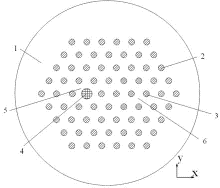
[0038] Such as figure 1 As shown, the matrix material 1 of the dual-core optical fiber is pure quartz, the hole period Λ is 6.487 μm, the diameter of the dielectric rod 4 is 4.925 μm, the diameters of the filling hole 3 and the air hole 2 injected into the sample to be tested are both 3.2435 μm, and the dielectric rod 4 has a diameter of 3.2435 μm. The refractive index of the rod 4 is 0.01 lower than that of the matrix material, and the refractive index of the sample to be tested is 1.33. From figure 1 It can be seen that the fiber core 5 is composed of pure quartz matrix material and the dielectric rod 4; the function of the seven air holes in the microstructure fiber core 6 is to inject the sample to be tested. The relationship between the effective refractive index of the mode in the core 5 and the microstructured core 6 with the normalized frequency is as follows: Figure 4 shown. It can be seen from the figure that the relationship between the two curves is the sam...

Embodiment 2

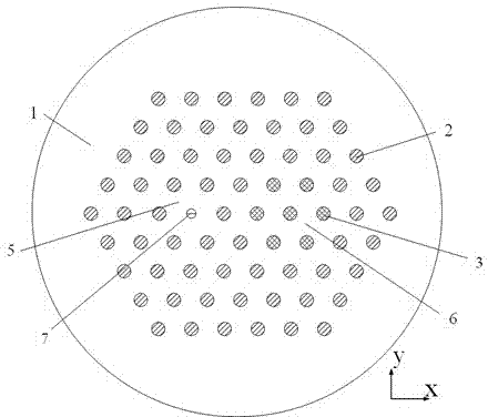
[0040] Its cross-section is as figure 2 As shown, the structural matrix material 1 is quartz, the pore period Λ is 6.487 μm, the diameter of the small air hole 7 is 1.9461 μm, the diameters of the filling hole 3 and the air hole 2 injected into the sample to be tested are both 3.2435 μm, and the sample to be tested The refractive index of 1.33. From figure 2 It can be seen that the fiber core 5 is composed of pure quartz matrix material and small air holes 7; the function of the seven air holes in the microstructure fiber core 6 is to inject the sample to be tested. The relationship between the effective refractive index of the mode in the core 5 and the microstructured core 6 with the normalized frequency is as follows: Figure 8 shown. It can be seen from the figure that the relationship between the two curves is like the second curve discussed above, and they have only one phase matching point in a wide frequency range. When the fiber length is taken as 20.33mm, a...


PUM

PropertyMeasurementUnit
pore sizeaaaaaaaaaa
refractive indexaaaaaaaaaa

Abstract

The invention discloses a two-core photonic crystal optical fibre refractive index sensor and a sensing system; the sensor comprises a cladding, a fibre core (5) and a micro-structural fibre core (6); a small air hole (7), the diameter of which is less than that of an air hole (2), or a medium rod (4), the refractive index of which is lower than that of a substrate material (1), is arranged in the fibre core (5); the micro-structural fibre core (6) is an area formed from seven filling holes (3) in an encircling manner; and the sensing system is composed of a board band light source, an optically coupled system, a photonic crystal optical fibre, a polarization controller and a spectrum detection system. The sensor and the sensing system are easy to inject a sample to be detected, so that the high-sensitivity refractive index detection is realized.

Description

technical field [0001] The invention relates to the field of optical fiber sensing, in particular to a dual-core photonic crystal optical fiber refractive index sensing and sensing system used in the fields of biology and medicine. Background technique [0002] Driven by the rapid development of optical communication, as a young member of sensors, fiber optic sensors are favored by more and more researchers due to their unique advantages in anti-electromagnetic interference, light weight, and sensitivity. At present, the development of optical fiber sensors is divided into two directions, principle research and application development. Because fiber optic sensing technology has not been industrialized as quickly as fiber optic communication technology, many key technologies are still in the laboratory prototype stage, and there is a certain distance from commercialization. Therefore, the principle technology of fiber optic sensing technology is still in a very important posi...

Claims


Application Information

Patent Timeline
Patent Type & Authority Applications(China)
IPC IPC(8): G01N21/41G02B6/02
Inventor 孙兵陈明阳张永康杨继昌
Owner JIANGSU UNIV
Why Eureka
Try Eureka