
Resistor manufacture device and production process thereof

A technology for manufacturing devices and resistors, which is applied in the manufacture of resistors, resistors, circuits, etc., can solve the problems of low material utilization and production efficiency, easy warping of sheet blanks, and high production costs, so as to improve material utilization and production Efficiency, guaranteed quality and performance, and the effect of reducing production costs

Inactive Publication Date: 2012-06-13
李永祥 +2
View PDF3 Cites 7 Cited by
  • Summary
  • Abstract
  • Description
  • Claims
  • Application Information

AI Technical Summary

Problems solved by technology

The main defects of this production method are: 1) The powder can only be directly pressed into the finished shape according to the size required by the design; 2) The sheet-shaped blank formed by direct pressing of resistance with a thickness below 10mm is easy to warp after sintering, and the product poor performance
If the warped product is used directly, there will be problems such as easy crushing during assembly, and insufficient contact of the end face, which will affect the electrical conductivity.
If the warped blank is ground to ensure the flatness of both ends, it will be easily broken during the grinding process, the scrap rate will be high, the material utilization rate and production efficiency will be low, and the production cost will be high; 3) When spraying metal aluminum, In order to prevent the aluminum powder from being sprayed on the outer circumference of the resistor and affect its insulation effect, it is often necessary to manually install a rubber sleeve on the circumference of the resistor, and then spray it; in the subsequent heat treatment process, the rubber sleeve must be manually peeled off , so time-consuming and labor-intensive, seriously affecting production efficiency
The above problems have been plagued by manufacturers and users, and have not yet been satisfactorily resolved.

Method used


Image

  • Resistor manufacture device and production process thereof
  • Resistor manufacture device and production process thereof
  • Resistor manufacture device and production process thereof

Examples


Embodiment Construction

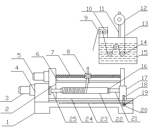
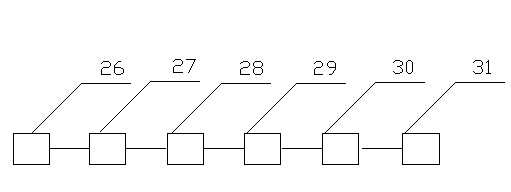
[0017] see figure 1 , figure 2 , The resistance manufacturing device of the present invention includes a mixing device 26 , a press 27 , a sintering device 28 and a heat treatment device 31 , and also includes a tape wrapping device 29 and a cutting device 30 . Wherein, the cutting device 30 is a wire cutting device, a water cutting device or a saw blade cutting device.

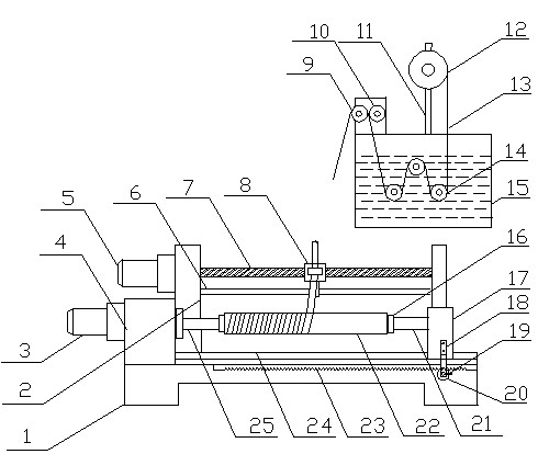
[0018] The tape wrapping device 29 is composed of a tape-carrying turntable 12, a dipping tank 15, a winding mechanism and a tape feeding mechanism, wherein the tape-carrying turntable 12 is installed above the dipping tank 15 through a bracket 11 for placing fibers belt 13. The tape feeding mechanism is located on one side of the winding mechanism and is fixedly connected with the winding mechanism for moving and guiding the impregnated fiber tape during the winding process.

[0019] The dipping tank 15 is provided with 1 to 3 dipping rollers 14, the dipping belt guide roller 9 and the scraping roller 10...


PUM


Abstract

The invention discloses a resistor manufacture device and a production process thereof. The resistor manufacture device is mainly characterized by comprising a belt winding device and a cutting device, wherein the belt winding device comprises a belt carrying rotating disk, a soaking trough, a winding mechanism and a belt sending mechanism; and the belt carrying rotating disk is arranged above the soaking trough through a bracket, and the belt sending mechanism is arranged on one side of the winding mechanism and fixedly connected with the winding mechanism. The resistor production process comprises the steps of: firstly, making a resistor into a columnar blank material with a length of 10-100mm, then winding a protective layer on the side surface of the columnar blank material and then cutting into sheet-shaped materials. Therefore, the edge of the resistor can be avoided being broken during cutting, the technical difficulty of easy warping of the resistor with a thickness of below 10mm is thoroughly solved in a sintering process, and quality and use performance of the resistor can be ensured reliably; meanwhile, rejection rate of the resistor in the production process can be greatly reduced, material utilization rate and production efficiency are increased, and production cost is decreased.

Description

technical field [0001] The invention belongs to the technical field of resistor production, in particular to a resistor manufacturing device and a production process. Background technique [0002] Resistors are the main components of lightning arresters, lightning arrester monitors, discharge counters, surge protectors, and varistors in power transmission and transformation systems. Their quality and performance are directly related to the reliability of power supply lines and electrical equipment overvoltage protection. And determine the safety of electrical products. At present, the production of resistance is to mix zinc oxide or strontium titanate as the main material with a binder, put it into a rigid mold, and press it together on the press through the pressure heads at the upper and lower ends to make a columnar blank or sheet. Then put it into a sintering kiln for sintering, and then arc spray metal aluminum or screen printing silver oxide paste on the end face, and...

Claims


Application Information

Patent Timeline
IPC IPC(8): H01C17/00
Inventor 李永祥
Owner 李永祥
Learn More