Compound full-power wind power converter

A wind power converter, full power technology, applied in the direction of converting AC power input to DC power output, converting AC power input to AC power output, wind power generation, etc., can solve the waste of resources, full power converter design and control Complicated, unable to adapt to new requirements and other issues, to achieve the effect of improving system reliability, facilitating system maintenance, and improving system reliability and stability

Active Publication Date: 2012-06-13
CHAJNA MAJNING DRAJVS EHND AUTOMEHJSHN KO +1
View PDF3 Cites 14 Cited by
  • Summary
  • Abstract
  • Description
  • Claims
  • Application Information

AI Technical Summary

Problems solved by technology

[0004] Most of the current mainstream wind turbines are 660V or 690V low-voltage systems. For high-power grid-connected converters, due to the limitation of the current level of power devices, parallel connection of converters or parallel connection of power devices is generally used to improve the efficiency of the converter. capacity, which complicates the design and control of full power converters for wind turbines
At the same time, the single-unit capacity of mainstream wind turbines at home and abroad has already exceeded 2MW, and the existing 5MW full-power converters mostly use back-to-back dual three-level four-quadrant operation converter solutions, but the back-to-back dual three-level structure The converter, for a full-power wind power generation system that does not require energy to flow in both directions, is a waste of resources
With the increase of wind turbine unit capacity and the reduction of wind turbine cost, new challenges will inevitably be posed to full power converters, and the existing technical solutions of full power converters can no longer meet the new requirements

Method used


Image

  • Compound full-power wind power converter
  • Compound full-power wind power converter
  • Compound full-power wind power converter

Examples


Embodiment Construction

[0020] The present invention will be further described below in conjunction with accompanying drawing.

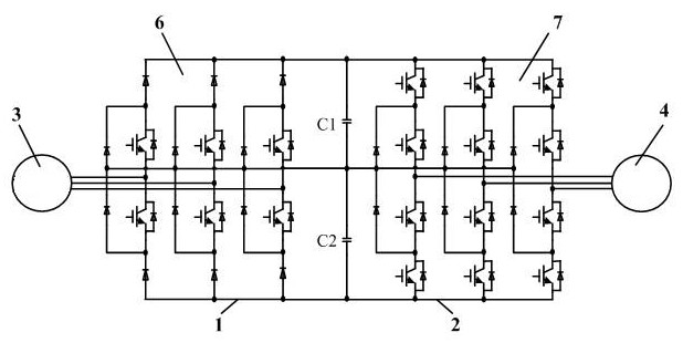
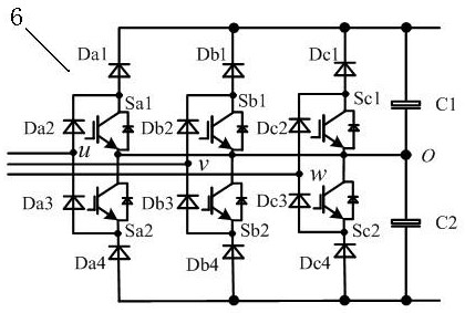
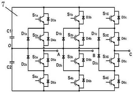
[0021] Such as figure 1 As shown, a composite full-power wind power converter includes a machine-side converter 1, a grid-side converter 2, a wind turbine 3, a power grid 4, and DC side filter capacitors C1 and C2. The machine-side converter 1 is composed of a two-quadrant three-level Vienna rectifier 6, and the grid-side converter 2 is composed of a voltage-type diode mid-point clamped three-level converter 7 using power devices with controllable switches. The AC input of the Vienna rectifier 6 The terminal is connected to the wind power generator 3, and its DC output terminal is connected to the DC bus side of the voltage-type diode mid-point clamped three-level converter 7 through the DC-side filter capacitors C1 and C2, and the voltage-type diode mid-point clamp type The AC side of the three-level converter 7 is connected to the grid 4 .

[0022] Vienna rectifier 6 in...


PUM


Abstract

The invention discloses a compound full-power wind power converter, belonging to the technical field of wind power generation and comprising a machine-side converter, a grid-side converter and a direct-current-side filter capacitor, wherein the machine-side converter is formed by a two-quadrant three-level Vienna rectifier; the grid-side converter is formed by a voltage-type diode neutral point clamped type three-level converter adopting a power device with a controllable switch; the alternating-current input end of the Vienna rectifier is connected with a wind power generator, and the direct-current output end of the Vienna rectifier is connected with the direct-current bus side of the voltage-type diode neutral point clamped type three-level converter by the direct-current-side filter capacitor; and the alternating-current side of the voltage-type diode neutral point clamped type three-level converter is connected with a power grid. The compound full-power wind power converter has the beneficial effects that the system structure is optimized, the cost is reduced, the system maintenance is convenient, the system reliability is improved, variable-speed constant-frequency controls of an electrically excited synchronous generator, a permanent magnet synchronous generator and a rat-cage type asynchronous generator are effectively realized, high-quality electric energy is provided, and the reliability and the stability of a power grid system are improved.

Description

technical field [0001] The invention relates to a wind power converter, in particular to a composite full-power wind power converter, which belongs to the technical field of full-power wind power generation systems. Background technique [0002] As global energy problems become more and more prominent today, wind energy, as a renewable, non-polluting energy with huge reserves, has been highly valued by human beings. Governments of various countries have even regarded this wind power generation, which is the most competitive with thermal power generation, as a way to promote power generation. An important way to diversify the structure and improve the environment and ecology. [0003] At present, wind turbines can be roughly divided into double-fed and full-power. Full-power wind power system is an important form of converting wind energy into electrical energy. Its simplicity, high efficiency, and easy realization of low-voltage ride-through are favored in the wind power fie...

Claims


Application Information

Patent Timeline
Patent Type & Authority Applications(China)
IPC IPC(8): H02J3/38H02P21/00H02M5/458H02M7/219H02M7/487
CPCY02E10/763Y02E10/76
Inventor 谭国俊李渊叶宗彬刘毅
Owner CHAJNA MAJNING DRAJVS EHND AUTOMEHJSHN KO
Why Eureka
Try Eureka