
Indirectly-connected micromechanical gyroscope with tuning fork vibration

A micro-mechanical gyroscope and vibrating technology, which is applied in the direction of gyroscope effect for speed measurement, gyroscope/steering sensing equipment, measuring device, etc. Effect of large stiffness ratio

Inactive Publication Date: 2014-08-13
SHANGHAI UNIV OF ENG SCI
View PDF5 Cites 0 Cited by
  • Summary
  • Abstract
  • Description
  • Claims
  • Application Information

AI Technical Summary

Problems solved by technology

Comb piezoresistive detection is detected by changing the distance between the comb teeth so that the capacitance changes. The damping is a typical pressure film damping, which affects the improvement of the system quality factor. The gyroscope using this detection method often needs vacuum packaging. Avoid the reduction of sensitivity; electrostatic comb capacitance detection is detected by the change of the overlapping area between the comb teeth, so that the capacitance changes. The damping is pressure film damping and sliding film damping. The existence of pressure film damping reduces the quality factor of the system possible, but mainly due to synovial film damping, which ensures a high quality factor for the system; parallel plate capacitance detection is similar to electrostatic comb capacitance detection, and capacitance detection is also realized by changing the overlapping area. The difference is that its damping belongs to Sliding film damping, no need for vacuum packaging, high sensitivity can be obtained under atmospheric pressure, the disadvantage is that the processing accuracy needs to be strictly controlled to ensure the alignment of the fixed grid and the movable grid

Method used


Image

  • Indirectly-connected micromechanical gyroscope with tuning fork vibration
  • Indirectly-connected micromechanical gyroscope with tuning fork vibration
  • Indirectly-connected micromechanical gyroscope with tuning fork vibration

Examples


Embodiment Construction

[0031] The indirect connection type tuning fork vibrating micromechanical gyroscope of the present invention will be further described below in conjunction with the accompanying drawings.

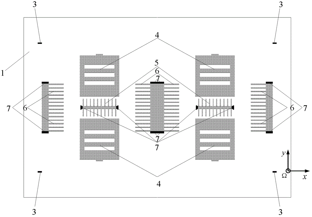
[0032] Such as figure 1 As shown, the first substrate 1 includes two groups of symmetrical detection grid-shaped fixed electrodes 4 , two detection comb-shaped fixed electrodes 5 , two groups of symmetrical driving comb-shaped fixed electrodes 6 , and fixed electrode anchors 7 .

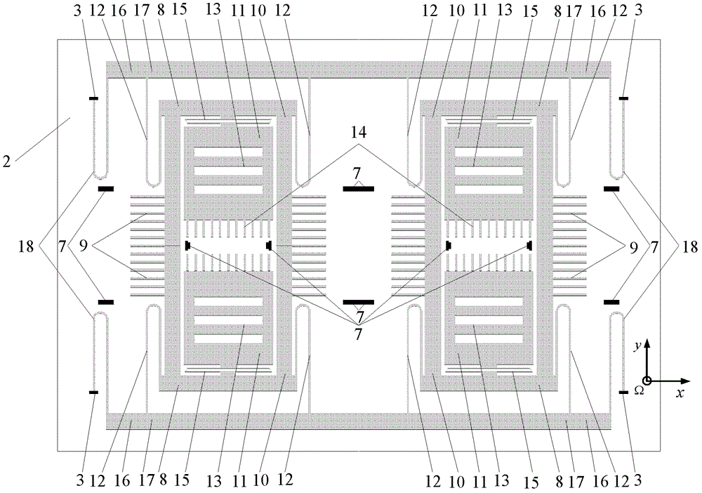
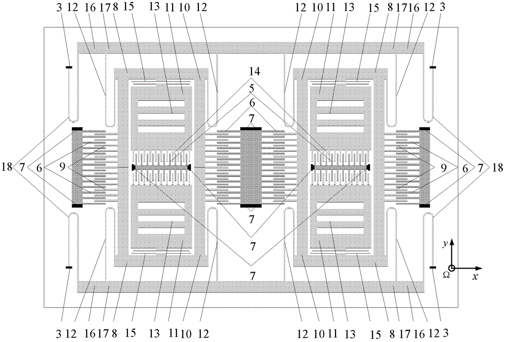
[0033] Such as figure 2 As shown, the second substrate 2 suspended above the first substrate 1 includes a symmetrical left structure 8 and a right structure and an intermediate structure 16 connecting the left structure 8 and the right structure; the left structure 8 or the right structure includes a belt drive comb 9 A drive mass 10, two proof masses 11, and four drive elastic beams 12, a proof mass 11 with a detection grid-shaped movable grid 13 and a detection movable comb 14 are located inside the drive mass...


PUM


Abstract

The invention relates to an indirectly-connected micromechanical gyroscope with tuning fork vibration, wherein the gyroscope is composed of a first substrate and a second substrate suspended above the first substrate, and the first substrate is fixed with the second substrate via four anchor points; the second substrate comprises a left structure and a right structure symmetrical with each other, as well as a middle structure connecting the left side with the right side; the left structure or the right structure comprises a drive mass block with drive comb teeth, two detection mass blocks and four drive elastic beams; the detection mass blocks for detecting a grid electrode with a movable grid shape and detecting movable comb teeth are located in the drive mass block and connected with the drive mass block via a detection elastic beam; and the middle structure comprises two middle coupling mass blocks connected with the drive elastic beams and four middle coupling elastic beams connected with the middle coupling mass blocks via four anchor points. The gyroscope is prepared by utilizing silicon micromachining technology, capable of obtaining high-flexibility and stable detection output in atmospheric environment, and capable of still keeping high accuracy and stability while being applied to complex environment.

Description

technical field [0001] The invention belongs to the field of micro-electro-mechanical systems, and relates to an indirect connection type tuning fork vibrating micro-mechanical gyroscope, in particular to a combination of left structure and right structure indirect connection, electrostatic comb driving, electrostatic comb capacitance and parallel plate capacitance. The detected and main damping is a tuning fork vibrating micromachined gyroscope with synovial film damping. Background technique [0002] The micromechanical gyroscope is a micro inertial sensor that uses the Coriolis effect to detect the angular velocity of a rotating object. Micromechanical gyroscopes prepared by microelectronic machining technology are widely used in aerospace, military, automotive, and consumer electronics products due to their low cost, small size, light weight, low power consumption, simple structure and process, and suitable for mass production. and other fields. The tuning fork vibrati...

Claims


Application Information

Patent Timeline
Patent Type & Authority Patents(China)
IPC IPC(8): G01C19/5621
Inventor 文永蓬尚慧琳
Owner SHANGHAI UNIV OF ENG SCI
Learn More