Portable lock-rotor temperature measuring device of motor
A technology of motor locked rotor and temperature measurement device, which is applied to measurement devices, electrical devices, motor generator testing, etc. and other problems, to achieve the effect of good maintenance, easy equipment maintenance and small size
- Summary
- Abstract
- Description
- Claims
- Application Information
AI Technical Summary
Problems solved by technology
Method used
Image
Examples
Embodiment 1
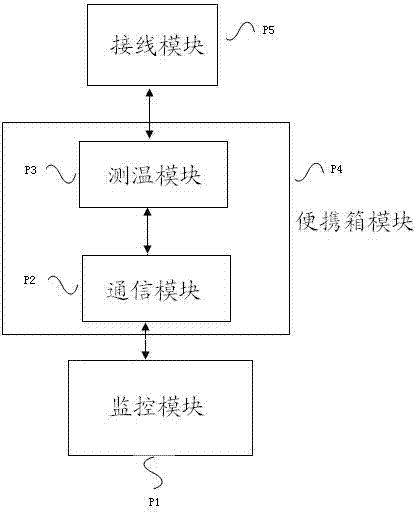
[0029] Embodiment one, see figure 1 As shown, a portable motor stall temperature measuring device in this embodiment includes a monitoring module P1, a communication module P2, a temperature measuring module P3, a portable case module P4, and a wiring module P5. The monitoring module P1 is used for automatic control of the whole device, the communication module P2 is mainly used for communication of the device, the temperature measurement module P3 is used for temperature collection of the whole device, and the portable box module P4 is used for Place the temperature measurement module, communication module and related operation buttons, etc., and the wiring module P5 is used for the connection of on-site electrical equipment.
Embodiment 2
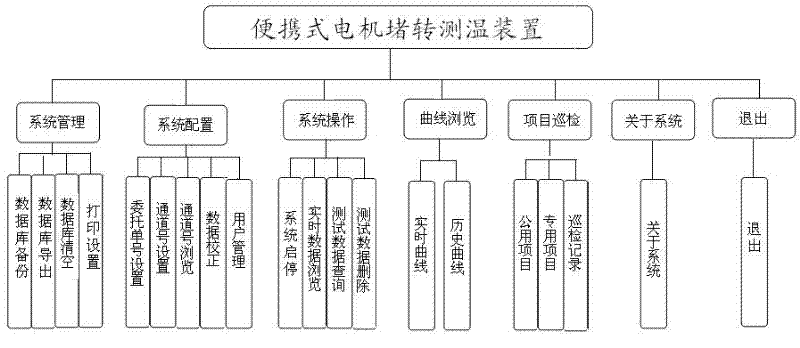
[0030] Embodiment two, see figure 2 As shown, this embodiment is a structural diagram of the monitoring software module of a portable motor stalled temperature measuring device; according to the specific situation of the motor temperature test when the stalled rotor is used, the control software of the device has seven functional modules, which are respectively "system management" , "System Configuration", "System Operation", "Curve View", "Project Inspection", "About System", "Exit". Key features include.
[0031] System management: "database backup", "database export", "database clear", "print settings".
[0032] System configuration: "order number setting", "channel number setting", "channel number browsing", "data correction", "user management".
[0033] System operation: "system start and stop", "real-time data browsing", "test data query", "test data deletion".
[0034] Curve browsing: "real-time curve", "historical curve".
[0035] Item inspection: "Public Items", ...
Embodiment 3
[0039] Embodiment three, see image 3 As shown, this embodiment is a test flow chart of an embodiment of a portable motor stall temperature measuring device. The test steps are as follows: Step 1: Select the test motor and set the motor in a locked-rotor state through the mechanical fixture, and then connect the J-type thermocouple in the experimental motor to the connection module (the total number of temperature measurement points of all motors shall not exceed 56);
[0040] The second step is to power on the system, start the test device, and conduct the motor stall temperature experiment according to the test process: (1) Fill in the task list, that is, the entrusted test order number, and the specific parameters are shown in Figure 4 of the attached drawing. (2) Then assign test channels. First, select "Order Number" in the list box on the left column, and then set the time interval in the "Collection Interval Settings" group box on the right, and set the channel number ...
PUM
 Abstract
Description
Claims
Application Information
 - R&D
- Intellectual Property
- Life Sciences
- Materials
- Tech Scout
- Unparalleled Data Quality
- Higher Quality Content
- 60% Fewer Hallucinations
Browse by: Latest US Patents, China's latest patents, Technical Efficacy Thesaurus, Application Domain, Technology Topic, Popular Technical Reports.
© 2025 PatSnap. All rights reserved.Legal|Privacy policy|Modern Slavery Act Transparency Statement|Sitemap|About US| Contact US: help@patsnap.com


