Automatic detection device of leakage rays in X-ray protective system

A protection system, X-ray technology, applied in the direction of radiation measurement, use feedback control, instruments, etc., to achieve the effects of high detection accuracy, precise positioning, and strong applicability

Active Publication Date: 2012-06-20
DANDONG HUARI SCIENCE ELECTRIC CO LTD
8 Cites 13 Cited by

AI-Extracted Technical Summary

Problems solved by technology

[0003] Aiming at the defects of the existing X-ray shielding protection outdoor radiation leakage detection, the present invention provides an automatic rad...

Abstract

The invention discloses an automatic detection device of leakage rays in an X-ray protective system. The automatic detection device is composed of an automatic detection car and a remote system control console, wherein the automatic detection car is composed of a travelling drive wheel, a gear steering device, a lifting transmission device, a back and forth expansion device and an angular deflection device; a leakage ray automatic feedback detector, an automatic spraying marking device and a real-time monitoring camera are arranged on the automatic detection car; and the remote system controlconsole is composed of a personal computer (PC), a programmable logic controller (PLC), a motion controller, a servo driver, a position encoder, a signal acquisition feedback chip and a timely monitoring imaging chip and the like. The automatic detection device provided by the invention has high automation degree, can be used for carrying out real-time leakage ray detection on a protective shieldroom at any angle, and has the advantages of precision positioning, strong applicability and high detection precision and the like. The automatic detection device has the characteristic of high safety performance because the condition that personnel is subjected to ray safety damage by accident can be fundamentally avoided in the remote control automatic detection; and the automatic detection device can be widely applied in manufacture factories and use factories of X-ray instruments, and detection epidemic prevention departments of each ray.

Application Domain

Technology Topic

Manufacturing FactoriesKinematic controller +12

Image

  • Automatic detection device of leakage rays in X-ray protective system
  • Automatic detection device of leakage rays in X-ray protective system
  • Automatic detection device of leakage rays in X-ray protective system

Examples

  • Experimental program(1)

Example Embodiment

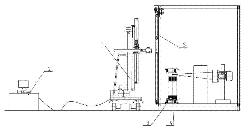
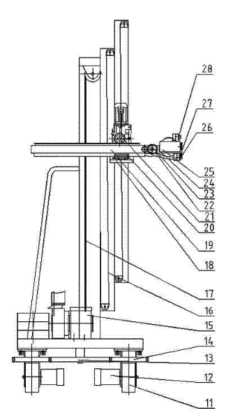
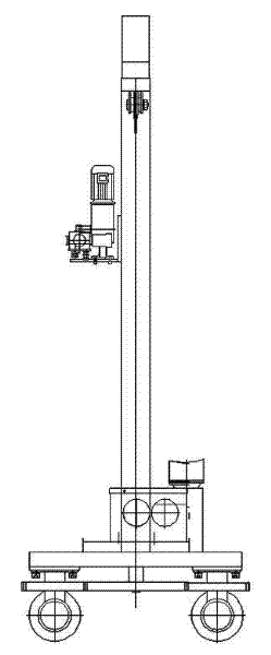
[0010] The structure of the present invention will be explained with reference to the drawings.
[0011] An automatic detection device for leaking rays in X-ray protection, such as figure 1 As shown, the automatic detection carriage 1 is placed near the shielded protective lead room 3 that needs to be detected. Connect to the remote control center. The X-ray machine system 4 in the shielding and protective lead room 3 is turned on to the maximum power working state for irradiation. After the automatic control carriage reaches the standard inspection position, the radiation leakage inspection starts. Synchronous storage of detection result data through real-time monitoring and synchronous feedback. According to the special location and key position of the shielding and protective lead room, such as the edge seam interface of the lead door 5 of the shielding and protective room, adjust the height, position and angle of the detection instrument to detect the radiation leakage in all directions.
[0012] Automatic detection of carriage 1 such as figure 2 As shown, the traveling drive wheel 11 is installed at the bottom of the automatic detection frame 1, the traveling drive wheel 11 is connected to the drive servo motor 12, and the gear steering device 13 is synchronized by the central main drive steering gear to synchronously engage the traveling drive wheel 11. Small wheels fixed on The gear 14 is equipped with a lifting transmission device 15 on the vertical frame of the detection carriage 1, and the lifting transmission device 15 is composed of a lifting guide rail frame 16, a wire rope 17 and a lifting fixing frame 18. One end of the wire rope 17 is connected to the reducer of the transmission motor, and the other end is connected to the lifting fixing frame 18. The lifting fixing frame 18 is equipped with front and rear telescopic devices 19, which are equipped with front and rear guide rail sliders 20 and drive motors on the telescopic rods. 21 and assemble the gear meshing rack, the front end of the telescopic rod of the front and rear telescopic device 19 is equipped with an angle deflection device 22, the angle deflection device 22 is equipped with a deflection gear 23, and a drive motor is installed, and the deflection seat 24 at the front end of the angle deflection device 22 is installed There is a leaked ray automatic feedback detector 25, a position measuring sensor 26 is installed on the deflection seat near the leaked ray automatic feedback detector 25, and an automatic spray marker 27 is installed on the deflection seat near the foremost end of the leaked ray automatic feedback detector 25 , A real-time monitoring camera 28 is installed on the side of the automatic spray marking device 27.
[0013] The remote system console 2 is composed of conventional PC, PLC, motion controller, servo drive, position encoder, signal acquisition and feedback chip, and timely monitoring and imaging chip. Connect the angle deflection device 22, the leaked radiation automatic feedback detector 25, the position measuring sensor 26, the automatic spray marking device 27 and the real-time monitoring camera 28 to the PC of the remote console 2 according to the usual circuit connection. PLC, motion controller, servo driver, position encoder, signal acquisition and feedback chip and signal input and output terminals of the imaging chip for timely monitoring. The position measuring sensor 26 accurately measures the distance from the surface of the object to be detected and the positional distance to the ground height, and feeds back the detection data to the remote console to determine the relative position of the detector from the surface of the object to be detected for calculation. The motion controller sends and receives pulses to drive each axis to complete the motion, while the servo motor encoder feeds back to the motion control. Through the final various drive control, the leaked radiation detector is precisely determined to be located in front of the wall to be tested. Among them, the traveling driving wheel 11 and the gear steering device 13 cooperate to make the detection carriage 1 move back and forth, left and right, and the lifting transmission device 15 and other mechanisms carry the detection instrument up and down to adjust and move. Mechanisms such as the front and rear telescopic device 19 carry the detection instrument to accurately adjust the distance to the detection object before and after, and the angle deflection device 22 adjusts the angle between the detection instrument and the detection object. The leaked radiation detector 25 detects the real-time X-ray dose received at the current location, and feeds back the detection data to the remote console to determine whether the leaked radiation meets national standards. If the leakage radiation dose in a certain place exceeds the national standard, the system will issue instructions to drive the automatic spray marking device 27 to move, and spray the color paint to adhere to the place where the leakage radiation exceeds the standard, and mark the leakage. The real-time monitoring camera 28 collects pictures of the scene situation and the surrounding environment in a timely manner, and transmits the pictures back to the remote controller as a reference for detection.
[0014] Detection principle process and flow.
[0015] First, place the automatic detection truck 1 near the shielded lead room 3 that needs to be detected for pre-positioning. Connect to the remote console, input the position of the point to be detected in advance in accordance with the requirements of the leakage detection standard and use the starting point coordinates as the reference zero point. The second step is to turn on the X-ray machine system 4 in the shielding and protective lead room 3 to the maximum power irradiation in the working state. The third step is that the remote system console 2 measures the data information of the height position feedback through the position measurement sensor 26, and after comprehensive calculation with the feedback information of the motion controller, servo drive, position encoder, etc., it automatically controls the front, rear, left, and right of the carriage according to the program control When walking reaches the position to be detected, the lifting transmission device 15, the front and rear telescopic device 19 and the angle deflection device 22 are driven to move, and the radiation leakage detector is accurately adjusted to the standard detection position. The fourth step is that the leaking radiation detector is turned on, and the detector receives the radiation dose in real time, and transmits the detected data to the remote system console 2 in real time. The fifth step is the dose detection and judgment. The PC will compare and judge the real-time detection data and the standard safety qualified data. When the detected dose exceeds the standard, the system will alarm and automatically drive and control the automatic spray marking device 27 to perform the defect location. Spray marks. When the detection structure meets the detection safety standard, the system controls the detection carriage to move in parallel or up and down to detect other areas to be detected in real time. The entire detection process adopts automatic control, and the detection screen is displayed on the PC through the real-time monitoring camera 28 for real-time manual monitoring. The inspection process is repeated in sequence until all inspections are completed, and the system collects inspection data and issues inspection reports in real time. Complete the entire remote automatic detection process.

PUM

no PUM

Description & Claims & Application Information

We can also present the details of the Description, Claims and Application information to help users get a comprehensive understanding of the technical details of the patent, such as background art, summary of invention, brief description of drawings, description of embodiments, and other original content. On the other hand, users can also determine the specific scope of protection of the technology through the list of claims; as well as understand the changes in the life cycle of the technology with the presentation of the patent timeline. Login to view more.

Similar technology patents

Targeted advertising by context of media content

InactiveUS20110179445A1Precise positioningWeight increaseElectronic editing digitised analogue information signalsUsing detectable carrier informationTargeted advertisingMedia content
Owner:TELEFON AB LM ERICSSON (PUBL)

Portable stand-alone device, particularly suitable for use in surgery, micro-component handling and the like

ActiveUS20140371761A1Minimal hand movementPrecise positioningMicromanipulatorDiagnosticsRotational degrees of freedomActuator
Owner:JUANPERA JESUS HERNANDEZ

Vehicle seat

Owner:TOYOTA BOSHOKU KK

Classification and recommendation of technical efficacy words

  • Strong applicability
  • Precise positioning

Intelligent assisted driving method and system

Owner:CHINA UNIV OF GEOSCIENCES (WUHAN)

Method and device for identifying image definition

ActiveCN105809704AIdentify wellStrong applicabilityImage enhancementImage analysisRegion of interestDistinctness of image
Owner:BEIJING XIAOMI MOBILE SOFTWARE CO LTD

Method and device for accurately positioning a patient in radiotherapy and/or radiosurgery

InactiveUS6865253B2Precise positioningGood flexibilityForeign body detectionRadiation beam directing meansX ray imageSoft x ray
Owner:BRAINLAB

Heart Valve Stent

InactiveUS20120283824A1Precise positioningSecure fixationSuture equipmentsStentsHeart chamberHeart valve stenosis
Owner:LUTTER GEORG +1
Why Eureka
Try Eureka