
Light quantizer based on four-wave mixing effect

A technology of four-wave frequency mixing and quantization, which is applied in the field of microwave photonics, can solve the problems of limited application range, difficult to meet requirements, and limited performance, and achieve the effects of strong controllability, fast sampling rate, and high resolution

Active Publication Date: 2012-06-20
山东中科际联光电集成技术研究院有限公司
View PDF2 Cites 1 Cited by
  • Summary
  • Abstract
  • Description
  • Claims
  • Application Information

AI Technical Summary

Problems solved by technology

With the rapid development of information technology in recent years, although traditional quantizers relying on electronic technology have developed to a certain extent, due to the limitation of electron mobility, they encounter electronic bottlenecks, which limit the further improvement of their performance and are difficult to meet the demand.
Quantizers based on superconducting materials require a low-temperature working environment, which limits their application range.

Method used


Image

  • Light quantizer based on four-wave mixing effect
  • Light quantizer based on four-wave mixing effect
  • Light quantizer based on four-wave mixing effect

Examples


Embodiment Construction

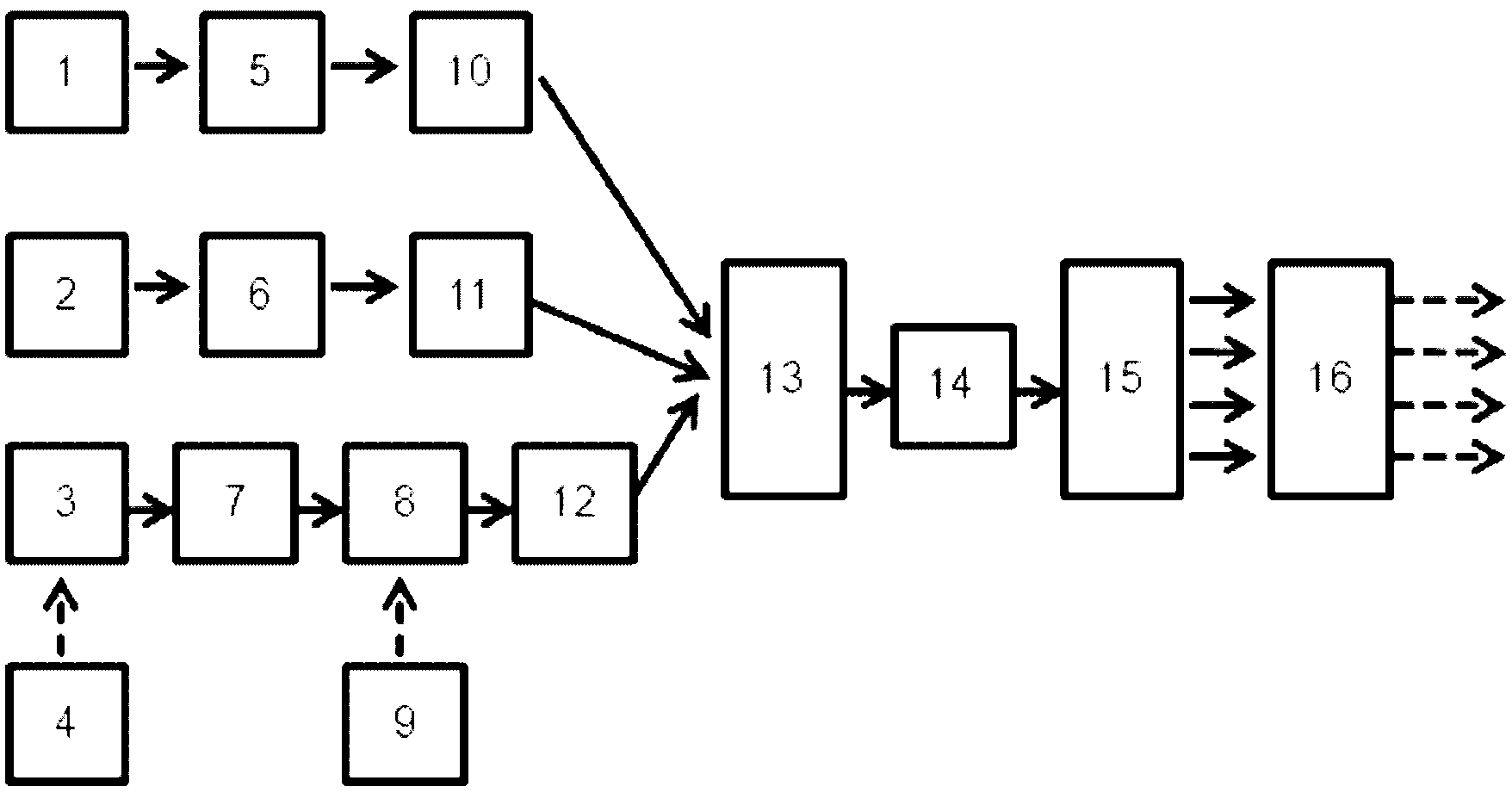
[0027] like figure 1 As shown, the present invention provides a kind of high-speed optical quantizer based on four-wave mixing effect, comprising:

[0028] A first optical pumping source 1, a second optical pumping source 2, and a sampling light source 3, the sampling light source 3 is a high-speed mode-locked laser, a high-speed pulsed laser based on a gain switch, or a laser-intensity modulator-based Phase modulator-a high-speed sampling pulse generating device formed by series connection of dispersive medium, its bandwidth is greater than twice the bandwidth of the microwave signal source 9 to be tested;

[0029] A high-speed microwave electrical signal source 4, the output end of the high-speed microwave electrical signal source 4 is connected to the input end of the sampling light source 3, and is used for adding the sampling signal to the sampling light source 3;

[0030] A first optical amplifier 5, a second optical amplifier 6 and a third optical amplifier 7, the inpu...


PUM


Abstract

The invention discloses a high-speed light quantizer based on a four-wave mixing effect. The light quantizer comprises a first optical pumping source, a second optical pumping source and a sampling light source, wherein the output end of a high-speed microwave electric signal source is connected with the input end of the sampling light source; the input ends of a first optical amplifier, a secondoptical amplifier and a third optical amplifier are respectively connected with the output ends of the first optical pumping source, the second optical pumping source and the sampling light source; the input end of a strength modulator is connected with the output end of the third optical amplifier; the output end of a microwave signal source to be tested is connected with the input end of the strength modulator; the input ends of a first polarization controller, a second polarization controller and a third polarization controller are respectively connected with the output ends of the first optical amplifier, the second optical amplifier and the third optical amplifier; the input end of a first waveguide array grating is connected with the output ends of the first polarization controller,the second polarization controller and the third polarization controller respectively; the input end of a nonlinear medium is connected with the output end of the first waveguide array grating; the input end of a second waveguide array grating is connected with the output end of the nonlinear medium; and the input end of a parallel high-speed optical detection array is connected with the output end of the second waveguide array grating.

Description

technical field [0001] The present invention relates to the field of microwave photonics, more particularly to optical quantizers for analog-to-digital conversion. Background technique [0002] High-speed, high-precision quantizers are widely used in high-speed communications, real-time monitoring, radar signal processing, image processing, and space communications, and are essential core devices in the field of information processing. With the rapid development of information technology in recent years, although traditional quantizers relying on electronic technology have developed to a certain extent, due to the limitation of electron mobility, they encounter electronic bottlenecks, which limit the further improvement of their performance and are difficult to meet the demand. However, quantizers based on superconducting materials require a low-temperature working environment, which limits their application range. Compared with traditional electrical quantizers, optical qu...

Claims


Application Information

Patent Timeline
Patent Type & Authority Applications(China)
IPC IPC(8): G02F1/365G02F7/00
Inventor 刘建国杜渊鑫王礼贤祝宁华
Owner 山东中科际联光电集成技术研究院有限公司
Learn More