Coupling peak absorption circuit at input end of motor

A technology of peak absorption and input terminal, applied in the field of motor control, can solve the problems of difficult to eliminate peak voltage pulses, large heat generation in the filter circuit, and increase the loss of high frequency energy of the fundamental wave. wildcard effect

Inactive Publication Date: 2012-06-20
中国兵器工业第二0五研究所
View PDF5 Cites 4 Cited by
  • Summary
  • Abstract
  • Description
  • Claims
  • Application Information

AI Technical Summary

Problems solved by technology

There are following problems in these two kinds of absorbing circuits: 1) system energy consumption increases
Since the current of the PWM fundamental wave is relatively large, the energy contained in its high-frequency component is much greater than the energy of the peak voltage, and the above filter circuit absorbs the high-frequency component of the PWM fundamental wave and the peak voltage pulse together, so the filter circuit will increase. High Frequency Energy Loss of Fundamental Wave
In addition, the filter circuit generates a lot of heat, and the power value of the resistor R in the filter circuit generally requires tens of watts to hundreds of watts, which is not good for the thermal effect design and energy consumption design of the instrument.
2) Filter circuit parameters are difficult to match
There are two reasons for this. One is that when the pulse width of the peak voltage is large, the corresponding main frequency is closer to the fundamental frequency, and the par

Method used


Image

  • Coupling peak absorption circuit at input end of motor
  • Coupling peak absorption circuit at input end of motor
  • Coupling peak absorption circuit at input end of motor

Examples


Embodiment Construction

[0019] The present invention will be further described in detail below in conjunction with the accompanying drawings and preferred embodiments.

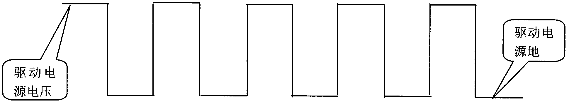
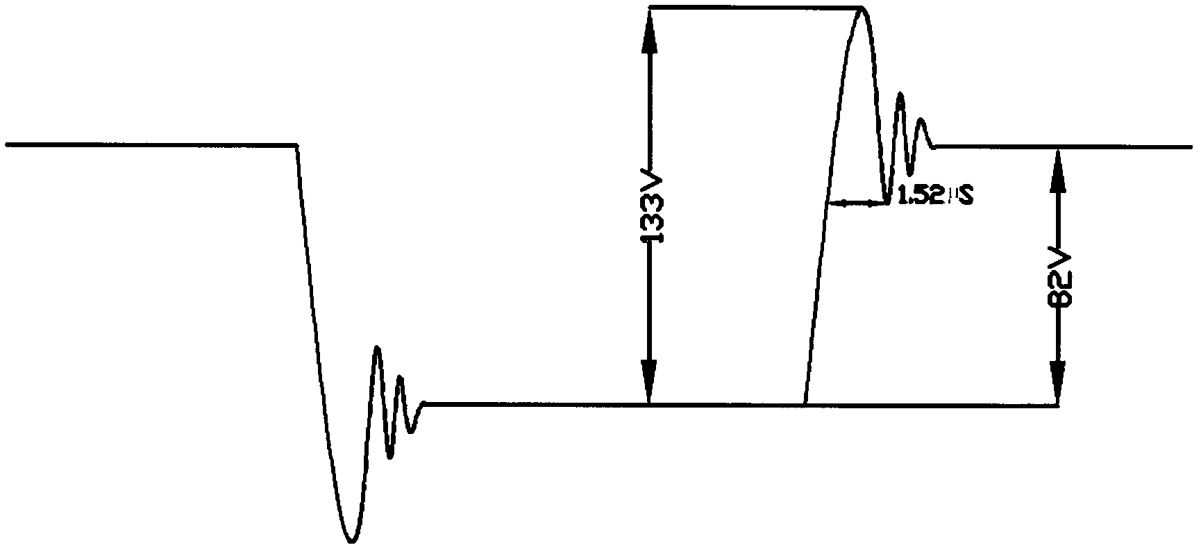
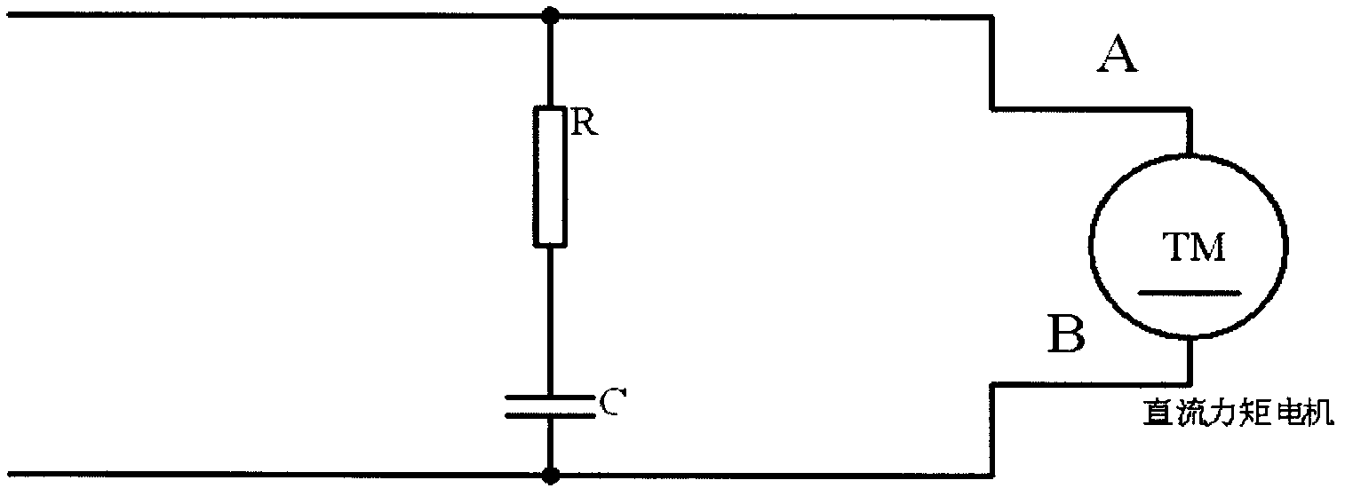
[0020] For a certain type of photoelectric turntable that uses PWM to drive the torque motor, its drive unit is about 55 meters away from the torque motor. When the photoelectric turntable has been used for one year, the insulation layer of the torque motor is broken down and the motor is damaged, and the two ends of the motor produce such figure 2 The voltage waveform shown, that is, coupled spikes are the main cause of torque motor reliability degradation. In order to solve the reliability problem of the torque motor, and avoid the side effects brought by the RC / LRC filter circuit on the photoelectric turntable. Therefore, the applicant considers adding a coupling peak absorbing circuit based on a fast recovery diode between the motor drive unit and the torque motor, and directly absorbs the coupling peak pulse at the input end o...


PUM


Abstract

The invention discloses a coupling peak absorption circuit at the input end of a motor, wherein the coupling peak absorption circuit is placed at the input end of the torque motor in a PWM (pulse width modulation) driving way and used for absorbing coupling peak voltage pulses at the input end of the motor. The absorption circuit comprises a voltage stabilizing circuit constituted by a plurality of capacitors connected in parallel and four fast recovery diodes, wherein the voltage stabilizing circuit is connected between a driving power supply and a power supply ground in parallel, the diodes are subjected to serial connection in pair and then connected at the two ends of the voltage stabilizing circuit, and the first and the second input ends of the motor are connected between the two diodes which are in series connection. The coupling peak absorption circuit disclosed by the invention is favorable for eliminating the impacts of the coupling peak voltage pulses at the end of the long-distance PWM driving motor on the reliability of the motor and simultaneously has the characteristics of low energy consumption, good compatibility, obvious wave absorption effect, low cost and the like.

Description

technical field [0001] The invention belongs to the field of motor control, and mainly relates to a motor input terminal coupling peak voltage pulse absorbing circuit, in particular to an absorbing circuit capable of suppressing the input terminal coupling peak voltage of a long-distance PWM driven motor. Background technique [0002] At present, the motor drive is mainly driven by PWM. The PWM driving method is to transmit a set of PWM carrier waves to the motor input terminal (see standard carrier waveform figure 1 ), drive the motor to rotate by controlling the duty cycle of the carrier. The PWM carrier mostly appears in the form of a square wave. [0003] In the design of the control system, it is often difficult to adopt an integrated design scheme for the drive control components and the motor, and in most cases they are connected by wires. When the connection line is too long, spikes will be coupled at the motor input (see figure 2 , the voltage waveform amplitud...

Claims


Application Information

Patent Timeline
IPC IPC(8): H02M1/14
Inventor 寿少峻陆培国赵创社王红红宋晓明刘小强邢军智李志宇柳井莉
Owner 中国兵器工业第二0五研究所
Why Eureka
Try Eureka