Magnetic stirring chaotic mixing method for laminar flow in microfluidic system and device thereof

A microfluidic system and magnetic stirring technology, applied in mixers, chemical instruments and methods, dissolution and other directions, can solve the problems of difficult effective mixing of laminar flow, and achieve the effect of reducing processing difficulty and simplifying the body structure.

Inactive Publication Date: 2012-06-27
JIANGSU UNIV
View PDF4 Cites 15 Cited by
  • Summary
  • Abstract
  • Description
  • Claims
  • Application Information

AI Technical Summary

Problems solved by technology

[0004] The purpose of the present invention is to solve the problem that the liquid in the microfluidic control system in the prior art is difficult to mix effectively due to laminar flow, and to prop

Method used


Image

  • Magnetic stirring chaotic mixing method for laminar flow in microfluidic system and device thereof
  • Magnetic stirring chaotic mixing method for laminar flow in microfluidic system and device thereof
  • Magnetic stirring chaotic mixing method for laminar flow in microfluidic system and device thereof

Examples


Embodiment Construction

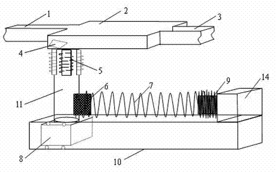
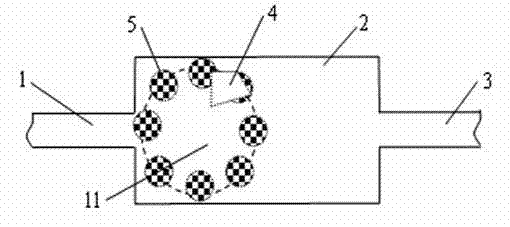
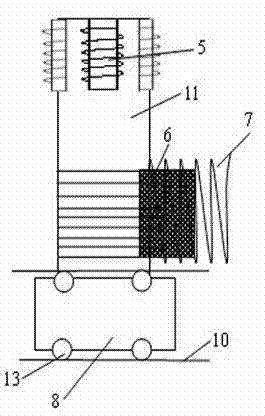
[0021] see figure 1 The schematic diagram of the overall structure of the laminar flow magnetic stirring chaotic mixing device of the microfluidic system of the present invention is shown. The microfluidic chip body can be placed through the chip frame, and the micro-magnetic stirrer 4 is placed in the mixing chamber 2 of the microfluidic chip. Inlet 1 or mixing chamber outlet 3 run out. At the bottom of the mixing chamber 2 of the microfluidic chip, a micro multiphase magnetic field timing generator 11 is vertically arranged, and the top of the micro multiphase magnetic field timing generator 11 is attached to the bottom surface of the mixing chamber 2 or close to the bottom surface of the mixing chamber 2 . The miniature multiphase magnetic field timing generator 11 is made up of a cylinder and multiphase miniature electromagnet group 5, the cylinder is perpendicular to the mixing chamber 2, the top of the cylinder is fixedly connected to the multiphase miniature electromag...


PUM

PropertyMeasurementUnit
Outer diameteraaaaaaaaaa

Abstract

The invention discloses a magnetic stirring chaotic mixing method for the laminar flow in a microfluidic system and a device thereof. The rotary vortex generation, the vortex magnitude and rotation direction in a mixing chamber can be indirectly controlled by utilizing a sequential rotating magnetic field generated by a miniature polyphase magnetic field sequential generator to control the motion of a miniature magnetic stirrer bar in the mixing chamber on the outside of the mixing chamber of a microfluidic chip. The bottom of the miniature polyphase magnetic field sequential generator is provided with a sliding dolly freely sliding in a slide way, the position of the rotation magnetic field is displaced through the resultant force of the attractive force of an electromagnet to a permanent magnet and the elastic force of a miniature spring, the overall rotation position of the stirrer bar in the mixing chamber is displaced through controlling the overall displacement of the bottom electromagnetic field, and multistage chaotic convection is rapidly formed in the stirring (mixing) chamber by utilizing the rapid change of the rotation position of the stirrer bar and the fluid rotation inertia, so the full liquid mixing is guaranteed, and a problem that the microscale liquid is difficult to effectively mix because of the laminar flow is solved.

Description

technical field [0001] The invention relates to a laminar flow mixing device and method in a microfluidic control system, which realizes mixing of fluids in a microfluidic mixing chamber. Background technique [0002] Mixing is a physical process whose purpose is to achieve a homogeneous partition of the different components involved in the process. Mixing is the most basic and necessary operation of any chemical and biochemical reaction. In macroscopic systems, mixing is usually accomplished by convection. In microfluidic chips, the structural size of the system is usually smaller than hundreds of microns, and the Reynolds coefficient of the fluid at the micron scale is very small ( R e≈0.1~100), turbulent mixing cannot occur, the fluid flows completely in a laminar state, and mixing can only be carried out by diffusion. Therefore, when the thickness of the microfluidic liquid layer is greater than the typical diffusion length, effective and rapid mixing is difficult to ...

Claims


Application Information

Patent Timeline
IPC IPC(8): B01F13/08
Inventor 张荣标杨宁
Owner JIANGSU UNIV
Why Eureka
Try Eureka