Efficient method for coating tail gas clean-up three-way catalyst

A three-way catalyst and exhaust gas purification technology, applied in physical/chemical process catalysts, chemical instruments and methods, catalyst activation/preparation, etc., can solve the problems of single exhaust gas control, high production cost, low production efficiency, etc. The effect of exhaust gas control function, improving production efficiency, and reducing the pressure of installation space

Inactive Publication Date: 2012-06-27
刘碧兰
View PDF7 Cites 8 Cited by
  • Summary
  • Abstract
  • Description
  • Claims
  • Application Information

AI Technical Summary

Problems solved by technology

[0011] According to the coating method of the above-mentioned patent documents 1-3, the common feature is that the catalytic properties of each coating are uniform along the axial direction of the carrier, and the exhaust gas control effect from the inlet to the outlet is single.
[0012] According to the coating method of the above-mentioned patent document 4, the characteristic is that it is coated on two carriers, which are actually front and rear catalysts. The disadvantages are that the system design, processing and packaging are more complicated, the production efficiency is low, and the production cost is high.

Method used


Image

  • Efficient method for coating tail gas clean-up three-way catalyst
  • Efficient method for coating tail gas clean-up three-way catalyst
  • Efficient method for coating tail gas clean-up three-way catalyst

Examples


Embodiment approach 1

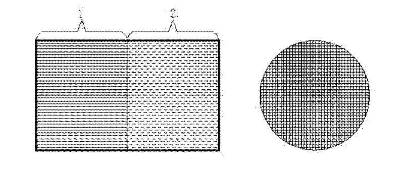
[0030] like image 3 Shown is a schematic diagram of the two-stage coating structure, the first coating 1 covers the half of the carrier at the upstream end of the exhaust gas flow, and the second coating 2 covers the half of the carrier at the downstream of the gas flow. After the first coating 1 is coated, the second coating 2 is applied, and then baked at a temperature of 500-600 degrees Celsius. In order to achieve the required coating load, the first coating 1 and the second coating are repeated. Layer 2 is applied and baked into shape. The catalyst raw materials, catalytic element concentrations and formulations used in the upstream and downstream coatings of the coating carrier are different, which need to be adjusted according to the emission characteristics of specific models. This makes it possible to obtain completely different catalytic properties in the axial direction of the support (airflow direction), greatly increasing the design scope and flexibility of mode...

Embodiment approach 2

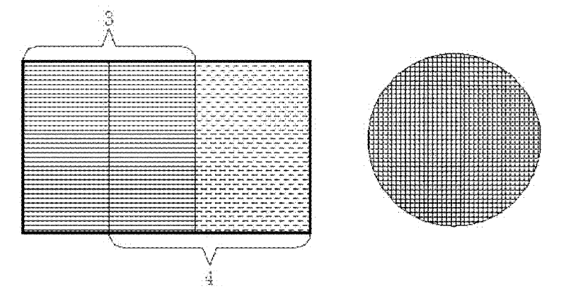
[0032] like Figure 4 Shown is a schematic diagram of the two-stage overlapping coating structure. The third coating 3 covers a large half of the carrier at the upstream end of the exhaust gas flow, and the fourth coating 4 covers a large half of the carrier downstream. Therefore, the middle section can have an overlapping coverage area. The specific coverage The length of the segment can be determined according to the exhaust gas control requirements. In this way, three different coating catalytic properties are actually formed along the axis of the carrier.

Embodiment approach 3

[0034] As shown in Figure 5, it is a schematic diagram of the three-stage three-stage coating structure. The coating method of the fifth coating 5 and the sixth coating 6 is similar to that of Embodiment 1, and the fifth coating 5 and the sixth coating 6 are coated. After firing, the seventh coating layer 7 is applied, and the seventh coating layer 7 covers most of the carrier at the upstream or downstream end. In this way, catalyst formulation coating materials with three different catalytic strategies can actually be used, and the functions of oxidation and reduction in the three-way catalyst can be optimally combined, and catalysts for special purposes (such as gasoline direct injection ignition engines) can also be used The NOxadsorber technology in GDI) is introduced into the single-support catalyst design, which brings great flexibility to the design.

[0035] The above-mentioned embodiment is just an example to help understanding of the present invention, and the presen...


PUM


Abstract

The invention discloses an efficient method for coating tail gas clean-up three-way catalyst, which specifically comprises the steps of two-segment twice coating, two-segment twice overlapped coating and the-segment three-times coating. By adopting the coating method, the water washed slurry formed of the catalysis elements, assistants and a number of oxides, which take different actions, is coated on a same carrier in a segmentation and layering manner, so that the same catalyst carrier takes the action of a front-stage catalyst and a rear-stage catalyst, and the tail gas control function is optimized, and the parts system installation space pressure is relieved. The coating method simplifies system design, improves production efficiency, and greatly reduces cost.

Description

[technical field] [0001] The invention relates to a method for coating a catalyst for purifying automobile exhaust gas, in particular to a new method for segmented and layered coating of a three-way catalyst for efficient exhaust gas purification. [Background technique] [0002] With the rapid increase of car ownership in the world, vehicle exhaust has become the main source of urban air pollution. According to relevant statistics, more than 90% of carbon monoxide, more than 60% of hydrocarbons and more than 30% of nitrogen oxides in urban air come from vehicle exhaust emissions. In order to control the air pollution caused by automobile exhaust, in addition to formulating strict emission standards, the research and development of automobile exhaust purification should also be strengthened. The traditional method of using a three-way catalyst for automobile exhaust control at home and abroad is to evenly coat a catalyst raw material mixed in a certain ratio on a ceramic or ...

Claims


Application Information

Patent Timeline
Patent Type & Authority Applications(China)
IPC IPC(8): B01J37/02F01N3/28
CPCY02T10/22Y02T10/12
Inventor 刘碧兰姚小刚
Owner 刘碧兰
Why Eureka
Try Eureka