Laser shock high molecular polymer indirect micro-forming method and dedicated device thereof

A polymer, laser shock technology, used in laser welding equipment, welding equipment, metal processing equipment and other directions, can solve the problems of reducing the strength and life of the mold, ablation of the surface of the parts, mold damage, etc., to reduce the phenomenon of dilution, Improve part quality and avoid ablation damage

Inactive Publication Date: 2012-06-27
JIANGSU UNIV
View PDF7 Cites 7 Cited by
  • Summary
  • Abstract
  • Description
  • Claims
  • Application Information

AI Technical Summary

Problems solved by technology

For example, the Chinese patent application number is 01134063.0, and the name is "a laser shock precision molding method and device". The laser is used to directly impact the parts to be processed, so that the parts are not uniformly stressed, and at the same time, the surface of the parts is ablated, and the surface quality of the parts is not high.
The Chinese patent application number is 200810023264.3, and the name is "a laser shock micro-volume forming method and device for micro-devices", which can realize micro-volume forming. It uses laser to drive the flyer, so that the flyer inherits the energy of the laser, thus avoiding laser The impact caused by direct impact on the workpiece, but the impact of the flyer is still a rigid impact, and the surface of the part will be etched, which will affect the surface quality of the part; at the same time, the size of the flyer is larger than the size of the workpiece, which will cause certain damage to the mold during the impact collision process. Reduce the strength and life of the mold; and during the rigid impact process, the phenomenon of metal dilution is serious, and the characteristics of the parts are reduced

Method used


Image

  • Laser shock high molecular polymer indirect micro-forming method and dedicated device thereof
  • Laser shock high molecular polymer indirect micro-forming method and dedicated device thereof
  • Laser shock high molecular polymer indirect micro-forming method and dedicated device thereof

Examples


Embodiment Construction

[0017] The technical scheme of the present invention is described in detail below in conjunction with accompanying drawing:

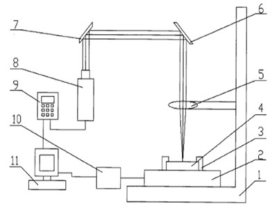
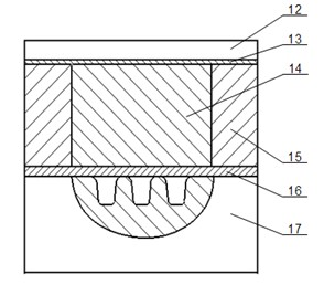
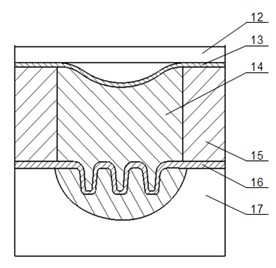
[0018] see figure 1 , The special device for indirect micro-forming of laser shock polymers of the present invention is composed of a laser loading system, a forming system and a control system. Among them, the laser loading system includes a nanosecond laser 8, a first reflector 7, a second reflector 6 and a focusing lens 5. The nanosecond laser 8 is equipped with an indicating light system, and the laser light emitted by it passes through the first reflector 7 and the second reflector in sequence. After reflection by the two reflectors 6, the optical path is changed to reach the focusing lens 5. The forming system includes a sample system 4, a clamp body 3, a three-dimensional mobile platform 2 and an L-shaped base 1, wherein the sample system 4 is arranged directly under the focusing lens 5, and the laser focused by the focusing lens 5 acts on th...


PUM


Abstract

The invention discloses a laser shock high molecular polymer indirect micro-forming method and a dedicated device thereof. A laser beam goes through an optical medium in a forming system and is exposed to an absorption coating film, so that a part of the absorption coating film is ablated to generate high-temperature high-pressure plasmas; the plasmas further absorb laser energy and then expand and explode; and the exploding plasmas expand towards the absorption coating film to generate a GPa-level impact pressure on the absorption coating film, resulting in plastic deformation of the absorption coating film. A high molecular polymer deforms towards a target work piece which is arranged at the lower part of the polymer under constraints of the impact pressure of the absorption coating film and the cavity of the high molecular polymer, resulting in plastic deformation of the target work piece. The method prevents ablative degradation or etching of the work piece surface and ensures precision forming of the work piece in the micro-mould.

Description

technical field [0001] The invention relates to the field of mechanical manufacturing, in particular to a laser shock polymer indirect micro-forming method and a special device thereof, which are suitable for micro-volume forming of complex devices that are difficult or impossible to form by conventional methods at the micro-scale. Background technique [0002] Miniaturized products have been widely used in many fields, such as micro-forming devices. Generally, the volume of micro-forming devices is relatively small, which makes its internal structure more complex than traditional forming equipment, and the precision required for parts is very high. It is difficult to manufacture micro-forming devices. . The current micro-forming device has the problems of high processing difficulty and low processing efficiency. At the same time, quasi-static plastic micro-forming is affected by the scale effect, and the material forming ability is reduced, which is difficult to meet the pr...

Claims


Application Information

Patent Timeline
Patent Type & Authority Applications(China)
IPC IPC(8): B21D22/10B23K26/00B23K26/04B23K26/046
Inventor 王霄杜道忠沈宗宝张虎李品胡杨高阳阳郭朝刘辉刘会霞
Owner JIANGSU UNIV
Why Eureka
Try Eureka