

Method for cutting ceramic by laser
A technology of laser cutting and ceramics, applied in the field of laser applications, can solve the problems of poor thermal stability, reduce the excellent performance of the substrate, and the laser energy cannot be effectively gathered, and achieve the effect of improving cutting efficiency and good cutting effect.
- Summary
- Abstract
- Description
- Claims
- Application Information
AI Technical Summary
Problems solved by technology
Method used
Image

Examples
Embodiment Construction
[0021] In order to describe the technical content, structural features, achieved goals and effects of the present invention in detail, the following will be described in detail in conjunction with the embodiments and accompanying drawings.
[0022] Laser processing technology is a technology that uses the characteristics of the interaction between the laser beam and the material to cut, weld, surface treat, drill, micro-process, and use it as a light source to identify objects, etc., for materials (including metals and non-metals). The largest field is laser processing technology. Laser processing systems include lasers, light guide systems, processing machine tools, control systems and detection systems.
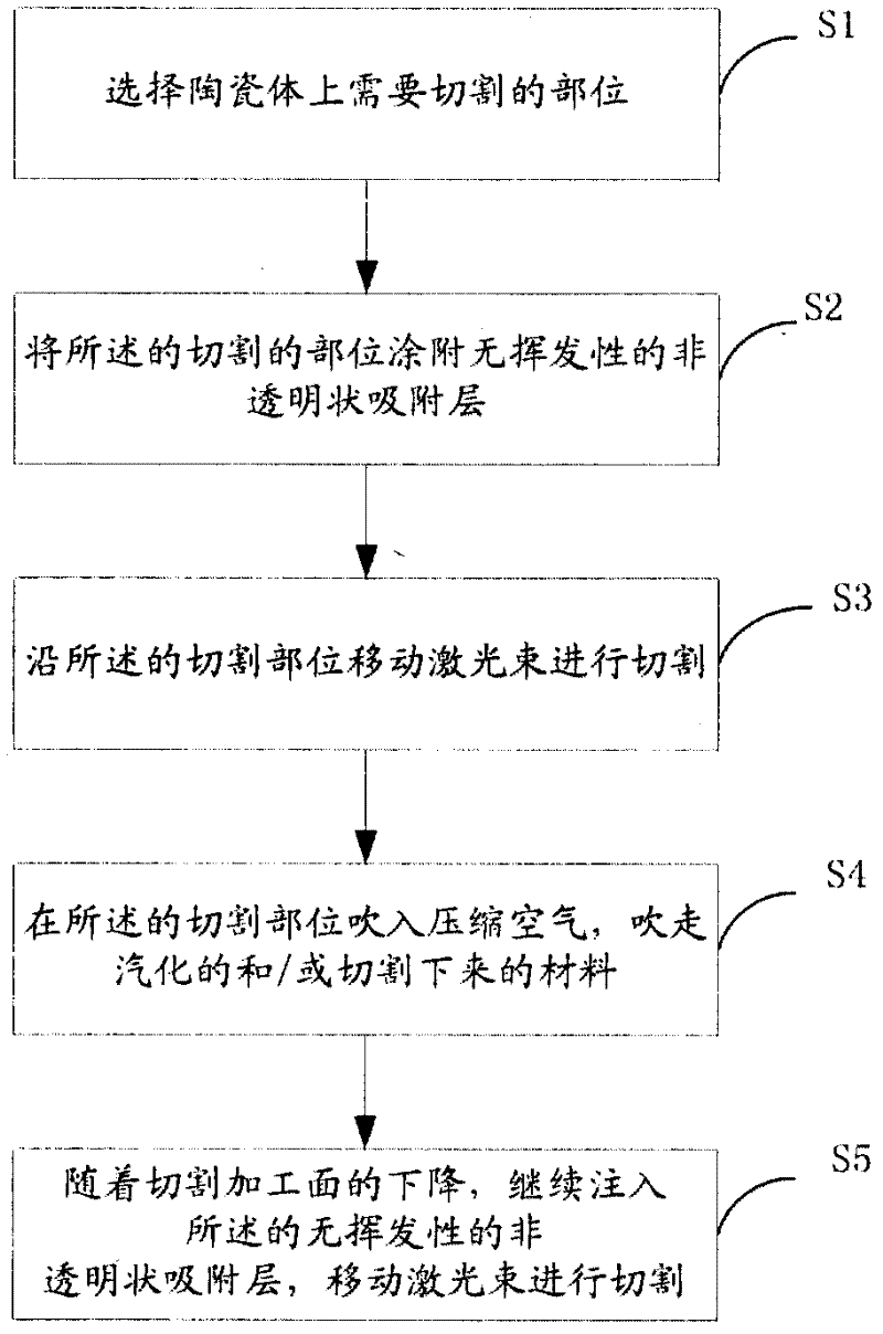
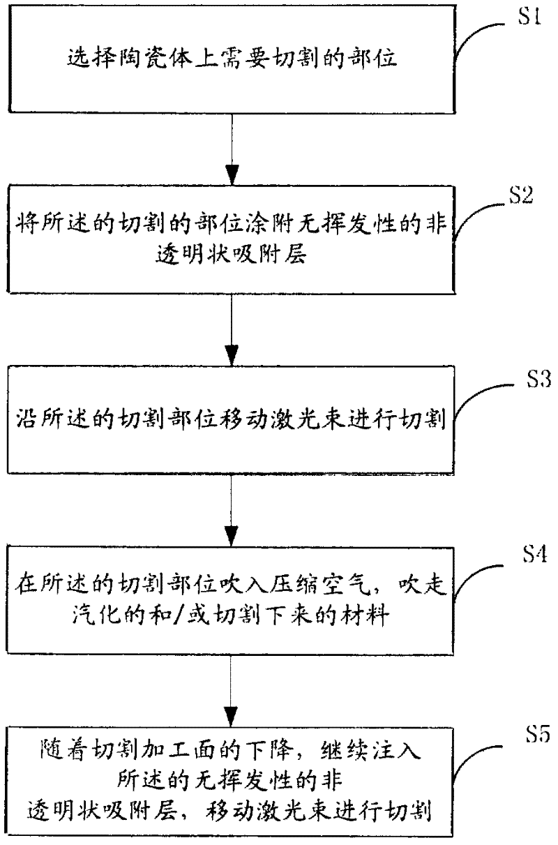
[0023] see figure 1 , a method of laser cutting ceramics, comprising:
[0024] S1. Select the part to be cut on the ceramic body;
[0025] The thickness of the ceramic body is: 0.1mm-2.0mm.
[0026] S2. Coating the cut part with a non-volatile, non-flammable, non-transpa...
PUM
| Property | Measurement | Unit |
|---|---|---|
| Thickness | aaaaa | aaaaa |
Abstract
Description
Claims
Application Information