Movable-arm-type powder bed powder spreading device

A technology of powder spreading device and moving arm, which is applied in the direction of loading/unloading, transportation and packaging, etc. It can solve the problems of low speed of powder spreading device, low material utilization rate, and affecting work reliability, so as to save the time of powder transportation, The powder spreading structure design is simple to ensure the smooth effect of powder spreading

Active Publication Date: 2012-06-27
HUAZHONG UNIV OF SCI & TECH
View PDF7 Cites 61 Cited by
  • Summary
  • Abstract
  • Description
  • Claims
  • Application Information

AI Technical Summary

Problems solved by technology

The powder spreading method is to spread powder while moving from left to right, the powder spreading stroke is long, and the powder spreading area occupied by the part forming area is small, and in order to ensure the stability and reliability of powder spreading, the speed of the powder spreading device is required to be low, so the powder spreading process It takes a long time, but the actual forming time of each layer section is relatively short, resulting in a waste of forming time
In addition, the existing powder spreading method is to spread the powder layer from the powder storage place all the way to the entire workbench, but in fact only the powder in the part forming area will be used, which causes most of the waste of materials, and the material utilization rate is relatively low. Low
[0007] (2) The powder spreading device is a rigid structure, which is easy to rub against the surface protrusions during the powder spreading process, which affects the stability of the powder spreading
However, the existing powder spreading devices such as powder spreading rollers and scrapers are all rigid structures, which are prone to serious friction with the protrusions during the powder spreading process, which not only shortens the service life of the powder spreading mechanism, but also affects the stability of the powder spreading. It may lead to the jamming of the powder spreading device, interrupt the forming process, and directly affect the accuracy and performance of the formed parts.
Usually we can manually adjust the height of the lower working table to make the powder spreading device pass smoothly, but this will increase the thickness of the powder layer, which will inevitably reduce the accuracy and forming quality of the formed part in the vertical direction
[0009] (3) The rapid prototyping environment of powder is poor, the structure of powder spreading equipment is more complicated, and the adhesion of powder affects its reliability
[0010] The environment for powder rapid prototyping is generally poor, and high-energy-density heat sources (such as lasers) are often required to melt or sinter the powder. These processes are accompanied by volatilization, splashing, etc., so the powder is easy to stick to bearings, hinges or moving parts. Affect the reliability of its work, or even hinder the normal operation of the equipment
If the structure of the powder spreading equipment is too complex and there are too many transmission and moving components, the adverse effects of harsh production conditions on these equipment will be more significant

Method used


Image

  • Movable-arm-type powder bed powder spreading device
  • Movable-arm-type powder bed powder spreading device
  • Movable-arm-type powder bed powder spreading device

Examples


Embodiment Construction

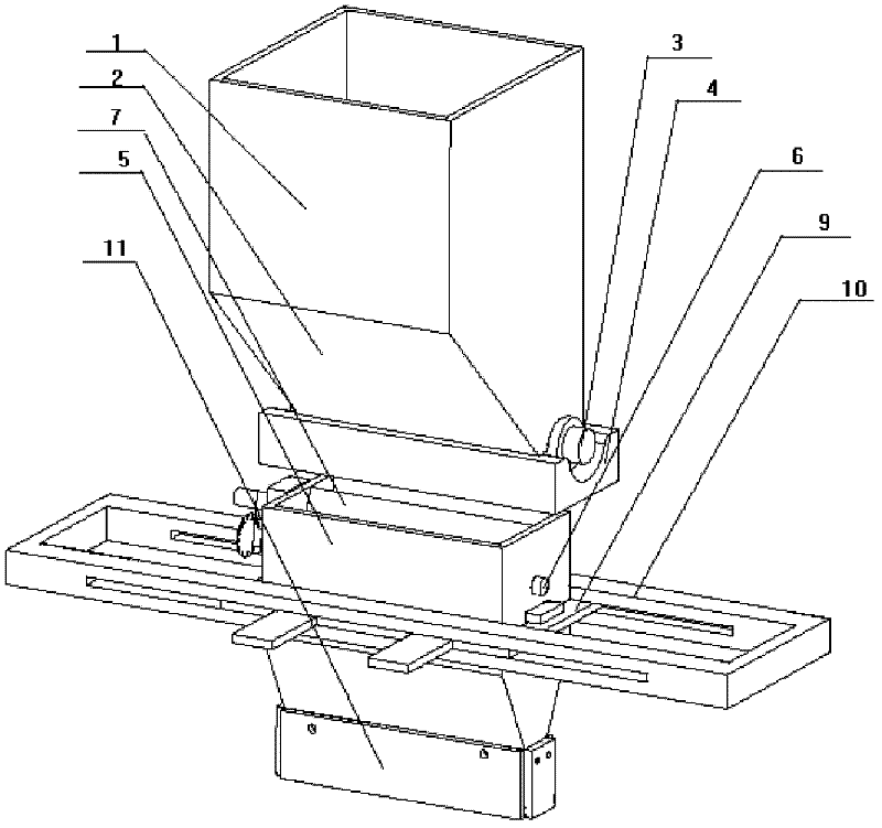
[0034] The device of the invention includes a quantitative powder feeding device, a transmission device and powder spreading equipment. The structure of each part of the present invention will be described in more detail below by means of examples, but the following examples are only illustrative, and the protection scope of the present invention is not limited by these examples.

[0035] Such as figure 1 As shown, the quantitative powder feeding device includes a powder storage box 1, a powder feeding roller 3, a fixed plate 4, and is equipped with a corresponding rotating motor. The powder storage box 1 is fixed above the working chamber. The powder storage box 1 is funnel-shaped. 4 is provided with a powder outlet corresponding to the powder outlet at the bottom of the powder storage box 1, which plays a role in quantitative powder feeding. The powder feeding roller 3 is installed between the powder outlet and the fixed plate 4, and is driven by an external rotating motor....


PUM


Abstract

The invention discloses a powder spreading device for rapid forming equipment. The device mainly comprises a quantitative powder conveying device, a movable silo, a movable arm, a movable frame and the like. The quantitative powder conveying device is used for supplying powder to the movable silo. Whether the powder falls down or not is controlled through a rotating sheet. According to the section of parts, the movable silo does regular translational motion within a working plane under the drive of the movable arm and the movable frame, and a scraper on the silo can realize dynamic powder spreading. By combining the movable arm and the movable silo with the movable frame, defining the powder within the area of the parts and adjusting the magnitude and the position of spread powder according to the change of the section of the parts, not only can the amount of the used powder is greatly saved, but also the powder spreading speed is high; and the structural design of the powder spreading device is simple, the powder spreading device is convenient to disassemble and assemble, the realization is easy, the cost is lower and the powder spreading device has an important application value to the improvement of the overall technical level of a powder bed quick forming technology.

Description

technical field [0001] The invention belongs to the field of advanced manufacturing, and in particular relates to a mobile arm type powder spreading device, which is mainly used for efficient powder spreading of rapid prototyping equipment. Background technique [0002] At present, the method of rapidly forming solid parts by using powder as forming material through selective deposition process is a research hotspot in the field of rapid manufacturing. Mainly include: selective laser sintering (Selective Laser Sintering, SLS), selective laser melting (Selective Laser Melting, SLM), direct metal powder laser sintering (Direct Metal Laser Sintering, DMLS), electron beam melting (Electron Beam Melting, EBM )Wait. Its process principle and flow: first, evenly spread a very thin layer of powder on the workbench; then, the computer controls the processing source (such as laser, electron beam, etc.) to partition the powder according to the cross-sectional data of the formed part. ...

Claims


Application Information

Patent Timeline
Patent Type & Authority Applications(China)
IPC IPC(8): B65G65/48B65G69/04B22F3/105
Inventor 魏青松史玉升薛鹏举贺文婷文世峰刘洁
Owner HUAZHONG UNIV OF SCI & TECH
Why Eureka
Try Eureka