
Quick cutter change milling rotor used on a pavement milling machine

A milling rotor and milling machine technology, applied in the field of milling rotors, can solve the problems of incomplete recycling of waste materials, affecting the quality of newly paved roads, and polluting the environment, so as to ensure the quality of road repairs, avoid waste materials splashing, The smooth effect of the spiral leaf surface

Inactive Publication Date: 2012-06-27
徐州昂拓机械科技有限公司
View PDF8 Cites 16 Cited by
  • Summary
  • Abstract
  • Description
  • Claims
  • Application Information

AI Technical Summary

Problems solved by technology

It often causes waste materials to splash and pollute the environment; in addition, waste materials cannot be completely recycled, and some waste materials fall into the ground groove after cutting, which affects the quality of the newly paved road surface

Method used


Image

  • Quick cutter change milling rotor used on a pavement milling machine
  • Quick cutter change milling rotor used on a pavement milling machine
  • Quick cutter change milling rotor used on a pavement milling machine

Examples


Embodiment Construction

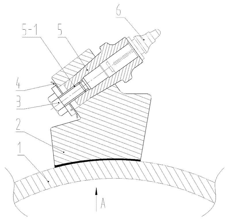
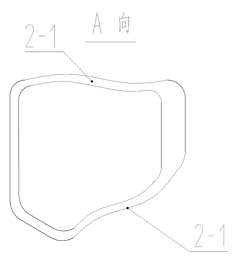
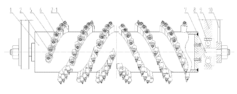
[0015] like figure 1 , figure 2 , image 3 Shown: a milling rotor used on a road milling machine that can quickly change tools, which includes: a cylinder 1, a base 2, a tool holder 5 and a tool head 6. The cylinder shaft 7 at both ends of the cylinder 1 is installed on the milling machine frame 9 through the bearing 8, the cylinder shaft 7 is connected with the power source of the milling machine through the belt 10, and the cylinder shaft 7 is connected with the power source of the milling machine. The power source obtains power to drive the barrel 1 to rotate at a high speed. The cutter head 6 is installed on the cutter holder 5 , and the cutter holder 5 is installed on the base 2 . The bases 2 are multiple, and the multiple bases 2 are divided into two groups, and the two groups of bases 2 are arranged in left-right symmetrical and opposite-handed helical lines, and the bottom surface of the base 2 is welded on the cylindrical surface of the cylinder body 1 .

[...


PUM


Abstract

The invention discloses a quick cutter change milling rotor used on a pavement milling machine, relating to an engineering machine. The quick cutter change milling rotor comprises a barrel, pedestals, a cutter sheath and a cutter head, wherein the lower part of each pedestal is a pyramid with large upper end and small lower end, the left side face and the right side face of the pyramid are manufactured into spiral faces, the left side faces and the right side faces of a plurality of adjacent pedestal are close to each other to form two groups of auger type spiral blade surface chains with opposite direction of turning, the spiral blade surfaces are flat and smooth and has small resistance, and waste materials are avoided from splashing and falling into troughs after milling. The cutter sheath and the pedestals are connected through conical degree to ensure concentricity and high strength, the cutting edge of the cutter head is maintained on the same spiral line to increase the flatness of the cut pavement, and the service life of the cutter head is prolonged. A threaded hole is arranged at the tail of the cutter sheath, the threaded hole fixes the cutter sheath on the pedestals through lock bolts and lock washers, and unsafe accidents caused by the dropping of the cutter sheath and cutter falling during use are avoided.

Description

technical field [0001] The invention relates to a paving machine, in particular to a milling rotor used on a road milling machine and capable of quick tool change. Background technique [0002] Road surface milling machine is the main equipment for road maintenance. The milling rotor rotates at high speed to mill and break the damaged asphalt pavement, cement pavement and various roadbeds, and then lay new road surface. The road milling machine requires that the end of the cutter head must be arranged according to the helical line, so as to ensure that the milled road surface is smooth, the cut marks are evenly distributed, and the fineness is conducive to the bonding of new materials. At the same time, the base is laid out into two sets of left-right symmetrical and opposite-spin helix lines, so that the inner surfaces of the base are connected to each other to form two sets of auger-type spiral blade chains with opposite rotation directions. The chains are concentrate...

Claims


Application Information

Patent Timeline
IPC IPC(8): E01C23/088
Inventor 姚费左振景
Owner 徐州昂拓机械科技有限公司
Learn More