Radiation enhanced LED (light-emitting diode) circuit board and manufacturing method and application thereof

A technology of LED circuit board and LED base, which is applied in printed circuit manufacturing, printed circuit, lighting and heating equipment, etc., can solve the problems of unreasonable position design of heat dissipation fins and poor heat dissipation effect, so as to improve heat dissipation effect and heat dissipation. Good effect, the effect of simplifying the process steps

Inactive Publication Date: 2012-06-27
王振辉
View PDF11 Cites 0 Cited by
  • Summary
  • Abstract
  • Description
  • Claims
  • Application Information

AI Technical Summary

Problems solved by technology

[0012] The invention provides a heat dissipation LED circuit board with good heat dissipation effect and its production method and application, which solves the problems caused by the bonding of the substrate and the heat sink through thermal conductive adhesive and the unreasonable design of the heat dissipation fin position in the existing LED circuit board. The problem of poor heat dissipation
The main body of heat dissipation plays the role of substrate and heat sink in the existing circuit board at the same time, so there is no problem that the heat conduction glue affects the heat export of the substrate caused by the heat conduction through the heat conduction glue, so that the heat dissipation is smooth

Method used


Image

  • Radiation enhanced LED (light-emitting diode) circuit board and manufacturing method and application thereof
  • Radiation enhanced LED (light-emitting diode) circuit board and manufacturing method and application thereof
  • Radiation enhanced LED (light-emitting diode) circuit board and manufacturing method and application thereof

Examples


Embodiment 1

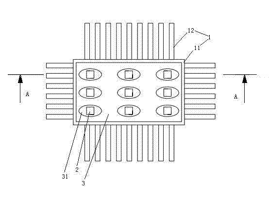
[0045] Embodiment one, see figure 1 , an LED circuit board with enhanced heat dissipation, comprising a heat dissipation main body 1 and a plurality of LED illuminants 2 .

[0046] The heat dissipation main body 1 is made of aluminum alloy.

[0047] The heat dissipation body 1 includes a base 11 and a plurality of heat dissipation fins 12 . The base body 11 is a quadrilateral plate structure. The heat dissipation fins 12 are distributed on the front, rear, left, and right sides of the base body 11 . The base body 11 and the cooling fins 12 are integrally structured.

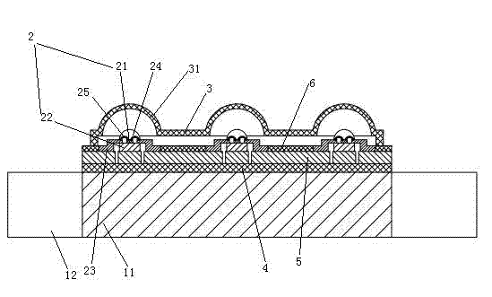
[0048] The LED illuminants 2 are arranged on the underside of the base body.

[0049] A light-transmitting plate 3 is provided on the underside of the base body 11 . A plurality of downwardly protruding cups 31 are provided on the light-transmitting plate 3 .

[0050] The cup body 31 is integrated with the light-transmitting plate 3 . The quantity of the cup body 31 is equal to the quantity of the LED illu...

Embodiment 2

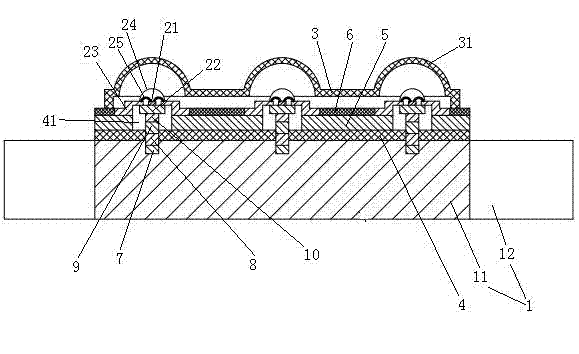
[0063] Embodiment two, see image 3 , the difference with Embodiment 1 is:

[0064] The heat dissipation main body 1 is made of aluminum.

[0065] Via holes 41 are provided on the insulating layer 4 . The through hole 41 cuts the conductive line 5 into two parts located on both sides of the through hole 41 . The through hole 41 protrudes into the interior of the base body 11 .

[0066] A zinc layer 7 , a nickel layer 8 , a copper layer 9 and a tin layer 10 are sequentially provided on the substrate 41 corresponding to the through hole 41 .

[0067] The LED base 22 is penetrated in the through hole 41 and soldered on the tin layer 10 .

[0068] The LED base 22 , the zinc layer 7 , the nickel layer 8 , the copper layer 9 and the tin layer 10 are separated from the conductive circuit 5 .

[0069] The two lead-out pins 23 of the LED illuminant 2 are connected to the two parts of the conductive circuit 5 located on both sides of the through hole 41 .

[0070] The manufacturin...

Embodiment 3

[0082] Embodiment three, see Figure 4 , The difference with the first embodiment is: the upper side of the base body 11 is provided with cooling ribs 13 . Of course, on the basis of the second embodiment, the heat dissipation ribs 13 can also be provided on the upper side of the base body 11 .


PUM


Abstract

The invention relates to LED (light-emitting diode) lighting. A radiation enhanced LED circuit board comprises an LED illuminant and a radiating main body; the LED illuminant comprises a PN (P-type semiconductor and N-type P-type semiconductor) junction and an LED base; the radiating main body comprises a base body and a radiating fin which are integral; an insulating layer is arranged on the base body; the PN junction is connected with the side of the base body, on which the insulating layer is arranged, through the LED base; a conducting circuit is arranged on the insulating layer; the PN junction is electrically connected on the conducting circuit; and the radiating fin is arranged on the side face of the base body, which is adjacent to the side face on which the LED base is arranged. The invention further discloses an LED lamp which comprises a counting rack and a plurality of radiation enhanced LED circuit boards. The radiation enhanced LED circuit board with good radiation effect and the manufacturing method and application thereof provided by the invention solve the problem of poor radiation effect of the conventional LED circuit resulted from unreasonable location design of the radiating fin and the bonding of a base plate and the radiator through heat conducting glue.

Description

technical field [0001] The invention relates to LED lighting, in particular to an LED circuit board with enhanced heat dissipation, a manufacturing method and application thereof. Background technique [0002] As a new generation of solid-state light source, LED has the advantages of long life, high efficiency and energy saving, small size, environmental protection and durability, and has been widely used in the field of display and lighting. [0003] The core part of the LED is the PN junction. When the injected electrons and holes recombine at the PN junction, the electrical energy is directly converted into light energy, but not all the converted light energy can be emitted outside the LED, and some of it will be converted into heat energy. This kind of heat energy has a huge side effect. If it cannot be effectively dissipated, it will increase the internal temperature of the LED, and the higher the temperature, the lower the luminous efficiency of the LED, and the faster...

Claims


Application Information

Patent Timeline
Patent Type & Authority Applications(China)
IPC IPC(8): F21V29/00F21V21/002F21S2/00H05K1/02H05K3/00F21Y101/02F21K9/00F21V29/76F21V29/89F21Y115/10
Inventor 王振辉
Owner 王振辉
Why Eureka
Try Eureka