Reciprocating motion friction experiment device

An experimental device and reciprocating motion technology, applied in the field of mechanical and material tribology research, can solve problems such as high cost and complicated technical process, and achieve the effects of easy operation, good interchangeability and easy maintenance

Active Publication Date: 2012-06-27
SHANGHAI UNIV
View PDF5 Cites 27 Cited by
  • Summary
  • Abstract
  • Description
  • Claims
  • Application Information

AI Technical Summary

Problems solved by technology

[0003] Surface texture preparation methods usually include reactive ion etching, LIGA technology, abrasive jet processing, laser texture processing technology, etc. DLC thin film preparation methods generally include physical vapor deposition and chemical vapor deposition, etc. These technologies are complex and costly. However, the surface texture and the DLC film itself have many influencing parameters. In order to study the tribological properties of the textured DLC film in a water-lubricated environment, a large number of friction and wear experiments are required.

Method used


Image

  • Reciprocating motion friction experiment device
  • Reciprocating motion friction experiment device
  • Reciprocating motion friction experiment device

Examples


Embodiment 1

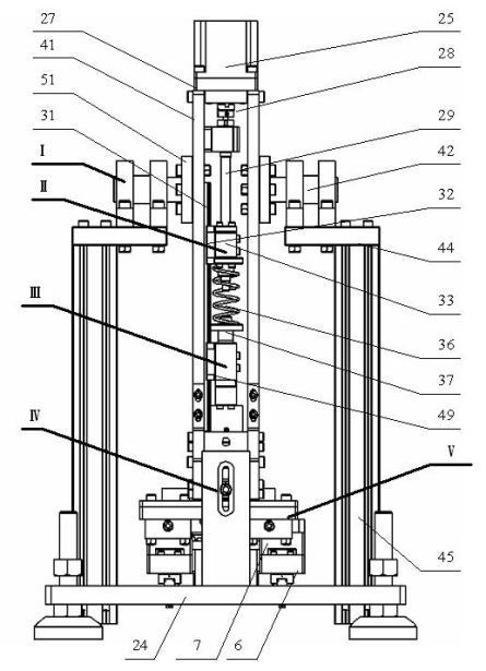
[0037] see figure 1 , figure 2 ,and image 3, the reciprocating motion friction test device includes a base (24), on which a reciprocating linear motion component (V) is installed, and a motion platform (9) is arranged on it, and on the motion platform (9) Experimental plate (17) is installed; there is a support component (I) fixedly installed on the base (24), on which there is a strip-shaped base plate (41) connected with the rotating shaft (42) to rotate around the rotating shaft, and the rotating shaft (42) The axis of the base plate (41) is perpendicular to the moving direction of the moving platform (9), and a transmission part (II) is fixedly installed on the upper part of the base plate (41), while a loading part (III) is slidably connected to the lower part; the loading part (III) The upper end is elastically connected to the lower end of the transmission part (II) through a spring (36) to form an elastic force loading; while the lower end is equipped with an exper...

Embodiment 2

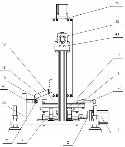
[0039] This embodiment is basically the same as Embodiment 1, and the special features are as follows: see figure 1 —— Figure 9 , the structure of the support member: the two rotating shafts (42) on the same axis are connected to the two strip-shaped left and right base plates (41) by bolts through the fixing plate (51), and the left and right base plates (41) is connected and fixed together with the upper and lower connecting plates (27), and the two rotating shafts (42) are respectively loaded on the two bearing seats (43) through two rolling bearings (50), and the two bearing seats ( 43) is respectively fixed on the base (24) through two mounting plates (44) and two brackets (45), so that the whole supporting part (I) can rotate around the rotating shaft.

[0040] The structure of the transmission part (II): a servo motor (25) is connected with the previous connecting block (27) through a mounting block (26), and fixed on the top of the supporting part (I), while the serv...

Embodiment 3

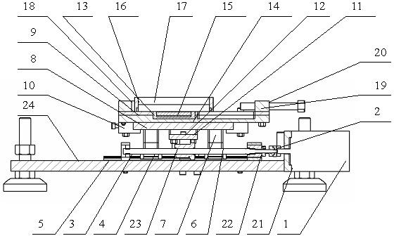
[0045] see figure 1 , figure 2 , image 3 , Figure 4 , including a supporting part (I), a transmission part (II), a loading part (III), a force measuring part (IV), and a reciprocating linear motion part (V). In the present invention, see image 3 , the test plate (17) is installed in the sealing ring (16), and fixed on the moving platform (9) by the clamping block (18) and the clamping bolt (20). The copper block (15) and the heating sheet (14) are fixed in the heat insulation block (13) and installed under the test plate (17), so as to realize the heating of the test block. The motion platform (9) is installed on the support platform (8) through the limit block (10), and the relative position relative to the support platform (8) can be adjusted. The support platform (8) is installed on the linear slider (4) through the connecting block (6) and the connecting block (7), so that the motion platform can perform reciprocating linear motion along the linear guide rail (5)....


PUM

PropertyMeasurementUnit
diameteraaaaaaaaaa

Abstract

The invention relates to a reciprocating motion friction experiment device. The device comprises a base and a force measuring part, wherein a linear reciprocating motion part is arranged on the base; a motion platform is arranged on the linear reciprocating motion part; an experiment disk is arranged on the platform; a support part is fixed on the base; a strip-type substrate connected with a rotating shaft is arranged on the support part and rotates around the rotating shaft; the axis of the rotating shaft is vertical to the motion direction of the motion platform; a transmission part is fixed on the upper part of the substrate; the lower part of the substrate is connected with a loading part in a sliding mode; the upper end of the loading part is elastically connected with the lower end of the transmission part through a spring to form elastic force loading; an experiment pin clamping piece is arranged at the lower end of the loading part; and the force measuring part includes a first force measuring sensor arranged between the spring and the loading part and a second force measuring sensor arranged between the base and the lower end of the substrate along the motion direction of the motion platform. A correlation between the motion and load of an experiment sample and frictional wear is measured through an experiment. The device has high compatibility and strong functions and is easy to operate and low in cost.

Description

technical field [0001] The invention relates to the field of mechanical and material tribology research, and provides a reliable, efficient and low-cost testing and evaluation platform for evaluating the friction and wear performance of new materials. Specifically relates to a reciprocating motion friction experiment device which can provide a platform for general pin-on-disk type tribology experiments. Background technique [0002] In recent years, with the gradual enhancement of people's awareness of environmental protection and the increasing emphasis on safe production, the traditional oil lubrication method is facing a serious test. Due to the characteristics of non-pollution, wide sources, energy saving, safety, and flame retardancy, water has become one of the lubricating media with great development potential. However, the low viscosity of water, poor lubricity, poor electrical conductivity, high gasification pressure, and large difference from oil lubrication m...

Claims


Application Information

Patent Timeline
Patent Type & Authority Applications(China)
IPC IPC(8): G01N3/56
Inventor 吴行阳黄夏婧黄元昊桑仁政张建华
Owner SHANGHAI UNIV
Why Eureka
Try Eureka