
Plasma facing experimental part with reference corner structure

A plasma and reference angle technology, applied in the direction of reducing greenhouse gases, instruments, nuclear reactors, etc., can solve the problems that affect the feasibility and accuracy of post-event analysis, and achieve the effect of avoiding surface inhomogeneity, convenient processing, and good contrast

Inactive Publication Date: 2012-06-27
INST OF PLASMA PHYSICS CHINESE ACAD OF SCI
View PDF4 Cites 4 Cited by
  • Summary
  • Abstract
  • Description
  • Claims
  • Application Information

AI Technical Summary

Problems solved by technology

[0005] The purpose of the present invention is to provide a plasma-facing experimental component with a reference angle structure, so as to solve the problem that the feasibility and accuracy of the post-analysis are greatly affected by the inhomogeneity of the surface of the experimental component in the prior art The problem

Method used


Image

  • Plasma facing experimental part with reference corner structure
  • Plasma facing experimental part with reference corner structure
  • Plasma facing experimental part with reference corner structure

Examples


Embodiment Construction

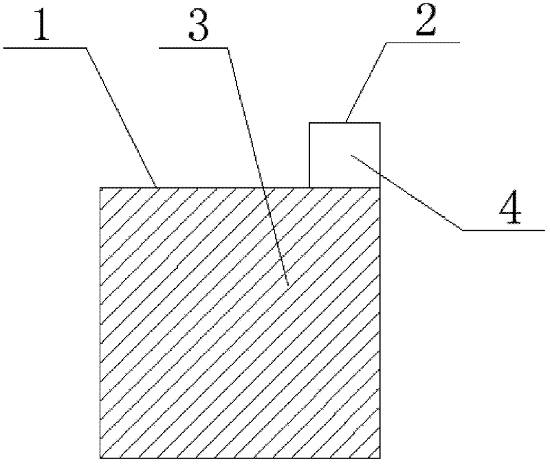
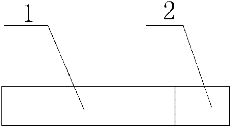
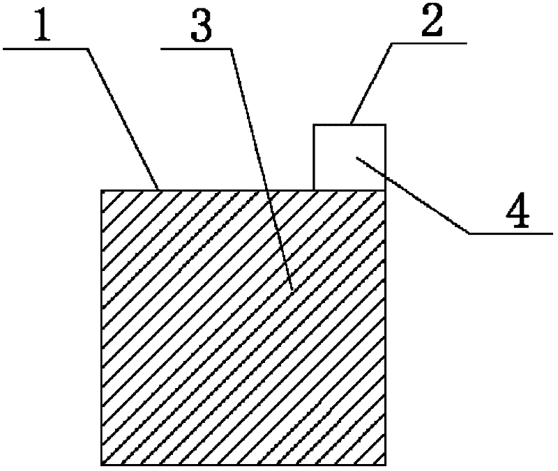
[0017] Such as figure 1 As shown, the present invention includes a test part 1 and a reference corner 2 arranged at one end of the test part 1 , and the reference corner 2 is a subtractive structure reserved on the test part 1 when the test part 1 is processed.

[0018] The material of the experimental component 1 is a plasma-facing material, preferably graphite, or molybdenum, or tungsten. During the experiment, the reference angle 2 is eliminated and embedded on the first wall of the tokamak device, and the surface is flush with the first wall.

[0019] One side of the reference angle 2 is used as the original surface 4, and one side of the experimental part 1 is used as the experimental surface 3. The same experimental marks are set on the original surface 4 and the experimental surface 3, and the surface part outside the experimental mark is the same as that in the experimental field. Other first walls or ordinary surfaces with the same divertor surface; the ex...


PUM


Abstract

The invention discloses a plasma facing experimental part with a reference corner structure. The plasma facing experimental part comprises an experimental part and a reference corner arranged at one end of the experimental part, wherein the reference corner is an attenuation structure reserved on the experimental part in the event of processing the experimental part; one surface of the reference corner is used as the original surface; one surface of the experimental part is used as an experimental surface; and a mark for experiments is arranged on the original surface. According to the invention, corrosion, deposition, impurity migration and retention of materials are represented by cutting off the reference corner, taking related data of the surface, the side surface and the body of plasma as original data, and referring and comparing the original data with the data of the experimental part subjected to a plasma irradiation experiment before carrying out the plasma irradiation experiment. The plasma facing experimental part has the advantages of being simple and easy for design, convenient for processing and better in comparison and can be applied to testing of a plasma facing material in a nuclear fusion experimental device and an interaction experiment between the plasma and a wall material.

Description

technical field [0001] The invention relates to a nuclear fusion experimental device, in particular to a plasma-facing experimental component with a reference angle structure. Background technique [0002] Materials are one of the key issues on the road to realizing fusion to the ultimate practical use. In the fusion device, the PFM directly faces the plasma and interacts with the plasma, which is prone to various PWI modification changes, which affects the service life of the PFM, and the escaping impurities may also endanger the stability of the plasma and the stability of the fusion device. Safe to run. The PWI problem is also considered to be one of the most critical issues in the construction of the International Thermonuclear Experimental Reactor (ITER) project. Its mechanism of action includes sputtering, injection, melting, evaporation, adsorption / desorption, Diffusion / capture, aggregation and foaming, hydrogen precipitation at grain boundaries, neutron irr...

Claims


Application Information

Patent Timeline
IPC IPC(8): G01N33/00G21B1/11
CPCY02E30/122Y02E30/10
Inventor 吴婧谢春意丁芳徐倩罗广南
Owner INST OF PLASMA PHYSICS CHINESE ACAD OF SCI
Features
  • Generate Ideas
  • Intellectual Property
  • Life Sciences
  • Materials
  • Tech Scout
  • Unparalleled Data Quality
  • Higher Quality Content
  • 60% Fewer Hallucinations
Learn More