Ring pillar for magnetic separation

A ring column and magnetic separation technology, which is applied in magnetic separation, solid separation, chemical instruments and methods, etc., can solve the problems of magnetite recovery rate decline, uneven horizontal distribution, and increased metal loss, etc., to improve recovery The effect of improving the efficiency, improving the utilization rate of magnetic energy, and enhancing the magnetic field force

Inactive Publication Date: 2012-07-04
UNIV OF SCI & TECH LIAONING
View PDF7 Cites 10 Cited by
  • Summary
  • Abstract
  • Description
  • Claims
  • Application Information

AI Technical Summary

Problems solved by technology

[0003] 1) In the original magnetic separation ring column design, each electromagnet ring yoke magnetic system is composed of four or six electromagnet cores with small excitation coils and a magnetic conduction ring yoke. The N and S poles of each electromagnet core Only one pole acts on the separation area of ​​the equipment, so the magnetic field energy of the original magnetic separation ring column acts on only 50% of the separation area, and there is still room for improving the utilization rate of magnetic energy;
[0004] 2) Each electromagnet ring yoke magnetic system in the rough selection area of ​​the original magnetic separation ring column can only produce four or six horizontally distributed N and S alternating point magnetic poles along the periphery of the separation cylinder, and there is a magnetic field that acts on the magnetic particles in the rough selection area The uneven force level distribution and blind area are not conducive to the magnetic particles in the ore slurry moving to the periphery of the roughing area under the action of the magnetic field force and entering the beneficiation area, which increases the magnetic particles entering the tailings inner pipe and becoming tailings Probability, it is easy to cause the increase of metal loss, the increase of tailings grade, and the decrease of magnetite recovery rate;
[0005] 3) The magnetic separation ring column has the problem of periodic fluctuations in tailings grade. The periodic fluctuation of tailings grade is consistent with the magnetic field cycle of the magnetic separation ring column equipment. The reason is that the outer cylinder of the magnetic separation ring column is located at the upper edge of the tailings inner pipe The magnetic system is periodically powered on and off. When the power is turned on, the magnetic particles brought out by the rising water flow in the selection area are controlled by the magnetic field force and cannot enter the tailings. When the power is turned off, the magnetic particles brought out by the rising water flow in the selection area It is washed into the tailings without being controlled by the magnetic field force, which causes periodic fluctuations in the tailings grade;
[0006] 4) Since the ore feeding pipe of the ore hopper is located in the center of the rough selection area of ​​the magnetic separation ring column equipment, the ore pulp can only enter from the center in the rough selection area, and the magnetic system is located on the outer periphery of the rough selection area. The magnetic effect of the magnetic force is gradually weakened from the outer periphery to the center, so there are uneven strength and blind areas in the distribution of the magnetic field force acting on the magnetic particles in the pulp, which affects and restricts the movement of the magnetic particles in the ore pulp to the outer periphery of the rough selection area, so that Part of the magnetic particles directly enter the inner tube of the tailings due to insufficient magnetic force and become tailings, resulting in the loss of valuable magnetic particles

Method used


Image

  • Ring pillar for magnetic separation
  • Ring pillar for magnetic separation
  • Ring pillar for magnetic separation

Examples


Embodiment Construction

[0023] The present invention will be further described below in conjunction with accompanying drawing.

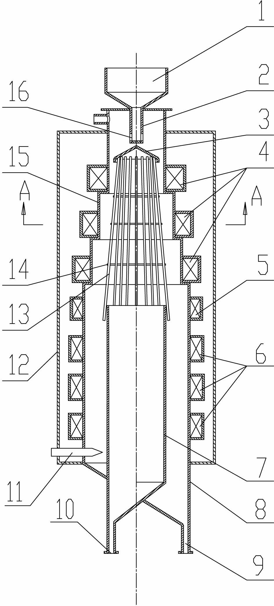
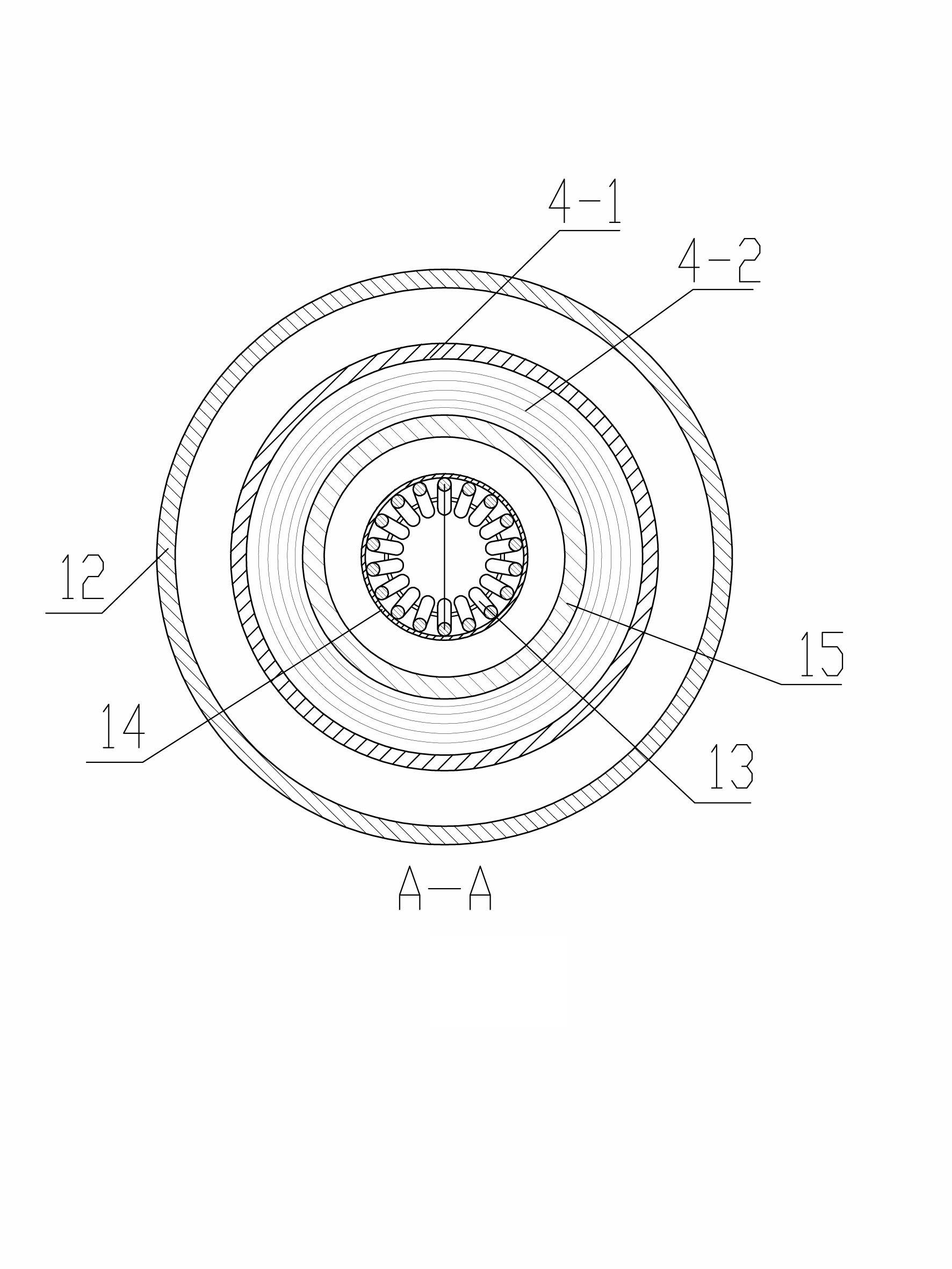
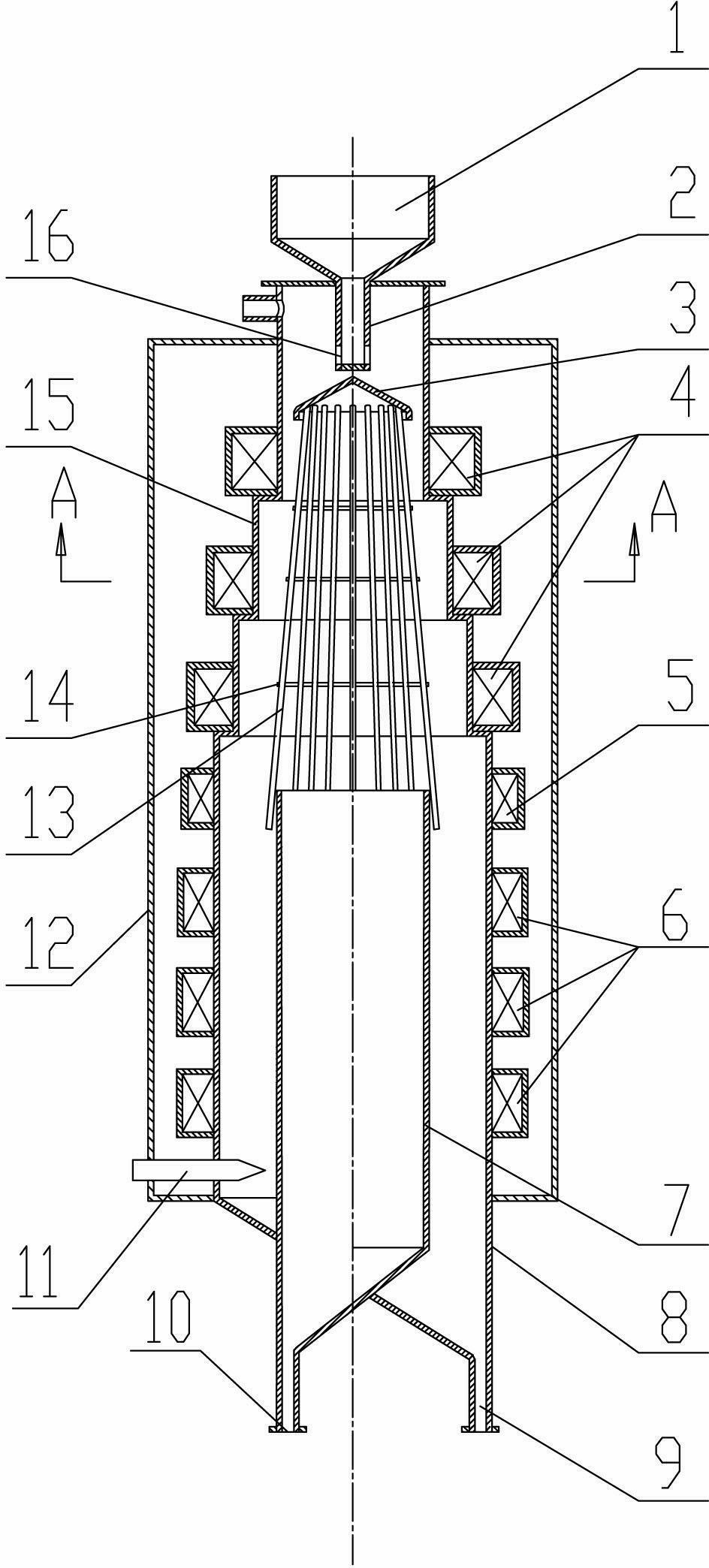
[0024] like figure 1 As shown, a magnetic separation ring column of the present invention includes an ore feeding hopper 1 with an ore feeding pipe 2, and a sorting tube connected to the lower end of the ore feeding hopper 1 is arranged on the outer surface of the sorting tube The magnetic system is set at the tailings inner tube 7 at the lower part of the sorting cylinder, the non-magnetic outer cover 12 fixedly connected with the upper and lower ends of the outer surface of the sorting cylinder and the electric control device connected with the magnetic system. device, the magnetic system is set in the non-magnetic outer cover 12, the bottom of the tailings inner pipe 7 is provided with a tailings outlet 10, the lower half of the sorting cylinder is provided with a water supply device 11, and the mine supply pipe 2 A group of ore feeding holes 16 are located in the lower...


PUM


Abstract

The invention belongs to the technical field of magnetic separation equipment and in particular relates to a ring pillar for magnetic separation. The ring pillar for magnetic separation comprises a mine feeding pipe, a mine feeding funnel, a separation barrel, a magnetic system, a tailing inner pipe, a non-magnetic conductive outer cover and an electric control device, wherein the separation barrel is composed of a step-shaped sleeve pipe, an equal-diameter sleeve pipe and a concentrate outlet; the pipe diameter of the step-shaped sleeve pipe is increased in sequence from top down, and the inner drift diameter of a small-diameter pipe at the uppermost part is the same as that of the tailing inner pipe; a peripheral mine separator and a magnetism gathering grating are arranged in the step-shaped sleeve pipe; the peripheral mine separator is arranged below the mine feeding pipe; the magnetism gathering grating is fixedly connected with the tailing inner pipe; and the magnetic system is composed of a coarse separation magnetic system, a commonly electrified coil magnetic system and a fine separation magnetic system which are respectively arranged on the step-shaped sleeve pipe and the equal-diameter sleeve pipe. According to the ring pillar for magnetic separation, the probability that magnetic particles in a coarse separation region directly enter in tailings is reduced, the probability that magnetic particles in a fine separation region are washed into the tailings with ascending water flow is reduced, the tailings grade is reduced, the recovery rate is increased, and the utilization rate of magnetic energy of equipment is maximized.

Description

technical field [0001] The invention belongs to the technical field of magnetic separation equipment, and in particular relates to a magnetic separation ring column. Background technique [0002] Chinese patent 03284502.2 is a new type of magnetic separation ring column. Although it solves the problems that the magnetic concentrator and magnetic separation column are not suitable for roughing operations and the water consumption is too large in the magnetite separation process, it has been used in industrial tests and There are also imperfections in production, which can be summarized as follows: [0003] 1) In the original magnetic separation ring column design, each electromagnet ring yoke magnetic system is composed of four or six electromagnet cores with small excitation coils and a magnetic conduction ring yoke. The N and S poles of each electromagnet core Only one pole acts on the separation area of ​​the equipment, so the magnetic field energy of the original magneti...

Claims


Application Information

Patent Timeline
Patent Type & Authority Applications(China)
IPC IPC(8): B03C1/26
Inventor 陈广振
Owner UNIV OF SCI & TECH LIAONING
Why Eureka
Try Eureka