Modeling method for axis-asymmetric end wall of annular blade grid of air compressor or turbine

A non-axisymmetric, annular blade cascade technology, applied in the direction of machine/engine, blade supporting element, mechanical equipment, etc., can solve the secondary flow loss and improve the efficiency, the effect is not significant, and the end wall structure cannot be flexibly constructed, Unable to give full play to problems such as non-axisymmetric end walls

Inactive Publication Date: 2012-07-04
NORTHWESTERN POLYTECHNICAL UNIV
View PDF5 Cites 11 Cited by
  • Summary
  • Abstract
  • Description
  • Claims
  • Application Information

AI Technical Summary

Problems solved by technology

The study pointed out that the non-axisymmetric end wall of the control curve in the form of trigonometric function in this method can reduce the secondary flow loss in the channel by 1%, and the efficiency is increased by 0.73±0.24%. Obviously, this method can reduce the secondary flow loss and the effect of improving efficiency is not significant
Moreover, only using trigonometric functions as the control function of the convex part

Method used


Image

  • Modeling method for axis-asymmetric end wall of annular blade grid of air compressor or turbine
  • Modeling method for axis-asymmetric end wall of annular blade grid of air compressor or turbine
  • Modeling method for axis-asymmetric end wall of annular blade grid of air compressor or turbine

Examples


Embodiment 1

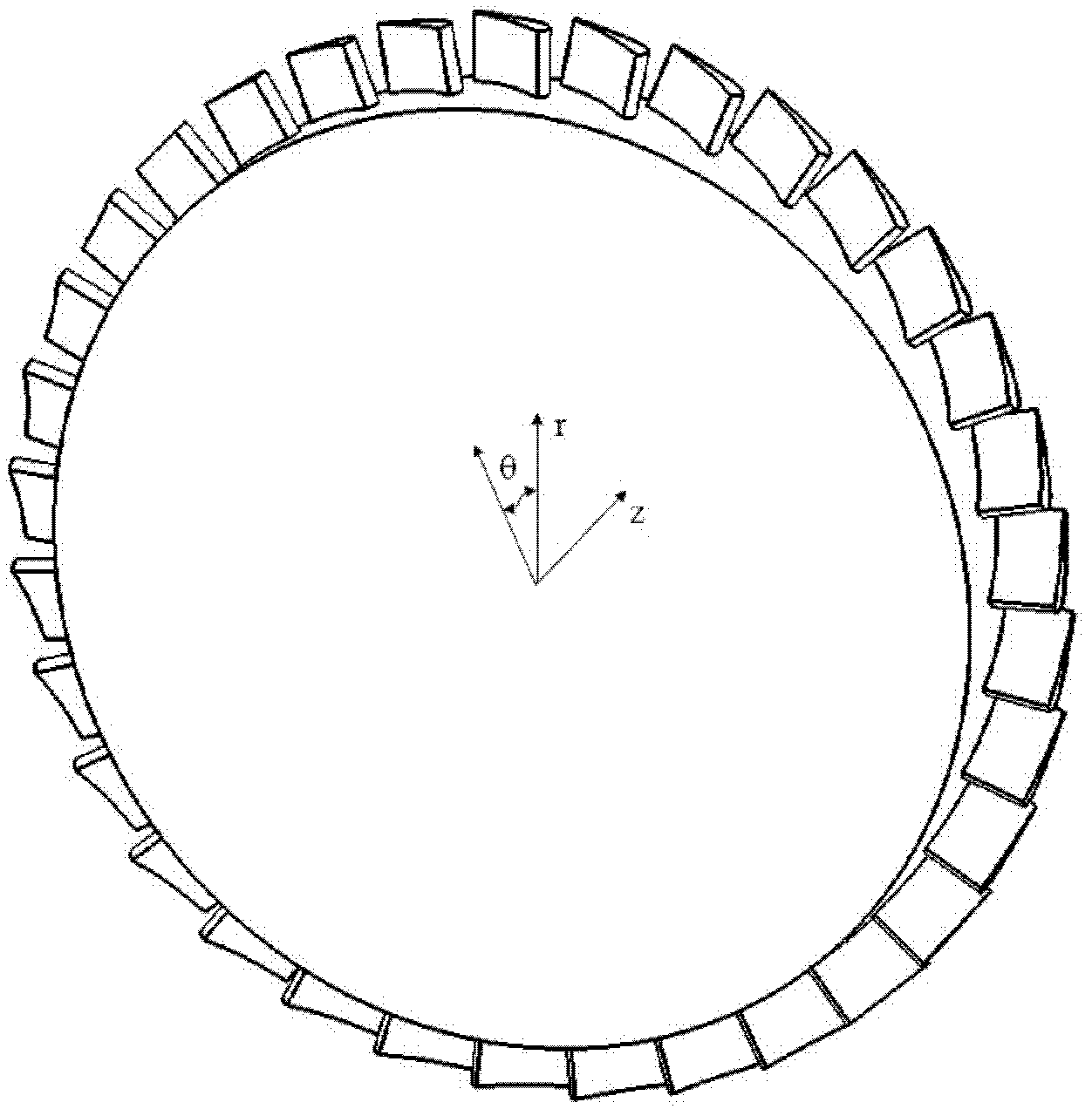
[0022] This embodiment is to construct a non-axisymmetric end wall of a turbine annular cascade, wherein the shape of the end walls between all adjacent blades on the turbine annular cascade is the same, and the end walls between adjacent blades are used as a shaped end wall cycle, there are several convex and / or concave structures in one molding end wall cycle, and the non-axisymmetric end wall with only one convex structure is constructed in this embodiment.

[0023] For a convex or concave structure follow the steps below:

[0024] Step 1: In a molding end wall cycle, at -10%C ax , 110%C ax , 0% grid pitch, and 100% grid pitch surround the end wall area as the modeling area of ​​the non-axisymmetric end wall, of which 0%C ax Indicates the position of the leading edge of the blade along the axial direction of the cascade, 100%C ax Indicates the position of the trailing edge of the blade along the axial direction of the cascade, 0% grid pitch indicates the position of the ...

Embodiment 2

[0031] This embodiment is to construct a non-axisymmetric end wall of a turbine annular cascade, wherein the shape of the end walls between all adjacent blades on the turbine annular cascade is the same, and the end walls between adjacent blades are used as a shaped end wall cycle, there are several convex and / or concave structures in one molding end wall cycle, and the non-axisymmetric end wall with only one concave structure is constructed in this embodiment.

[0032] For a convex or concave structure follow the steps below:

[0033] Step 1: In a molding end wall cycle, at -10%C ax , 110%C ax , 0% grid pitch, and 100% grid pitch surround the end wall area as the modeling area of ​​the non-axisymmetric end wall, of which 0%C ax Indicates the position of the leading edge of the blade along the axial direction of the cascade, 100%C ax Indicates the position of the trailing edge of the blade along the axial direction of the cascade, 0% grid pitch indicates the position of the...

Embodiment 3

[0040] This embodiment is to construct a non-axisymmetric end wall of a turbine annular cascade, wherein the shape of the end walls between all adjacent blades on the turbine annular cascade is the same, and the end walls between adjacent blades are used as a shaped end wall cycle, there are several convex and / or concave structures in one cycle of the shaped end wall, and the non-axisymmetric end wall with one concave structure and one convex structure is constructed in this embodiment.

[0041] For a convex or concave structure follow the steps below:

[0042] Step 1: In a molding end wall cycle, at -10%C ax , 110%C ax , 0% grid pitch, and 100% grid pitch surround the end wall area as the modeling area of ​​the non-axisymmetric end wall, of which 0%C ax Indicates the position of the leading edge of the blade along the axial direction of the cascade, 100%C ax Indicates the position of the trailing edge of the blade along the axial direction of the cascade, 0% grid pitch ind...


PUM


Abstract

The invention provides a modeling method for an axis-asymmetric end wall of an annular blade grid of an air compressor or a turbine. The method comprises the following steps: firstly, zoning modeling zones of a convex part structure or a concave part structure; modeling a convex part control curve or a concave part control curve in the axial direction of the blade grid or the circumferential direction of the blade grid; and finally modeling a curved surface control function in the radial direction of the blade grid. The invention particularly provides a novel convex part or concave part control function. Through the adoption of the method, the axis-asymmetric end wall of the annular blade grid of the air compressor or the turbine can be modeled conveniently and flexibly; and through the adoption of the axis-asymmetric end wall, the pressure gradient in a passage can be reduced effectively, the airflow at the exit of the passage can be more uniform, the total pressure loss coefficient in the passage can be reduced considerably, the secondary flow loss in the passage can be reduced, and further the performance of the blade grid of the air compressor or the turbine can be improved.

Description

technical field [0001] The invention relates to the technical field of aero-engine design, in particular to a method for modeling a non-axisymmetric end wall of a compressor / turbine annular blade cascade. Background technique [0002] The development of modern high-performance aero-engines requires higher efficiency of its key components, the compressor / turbine. Reducing compressor / turbine cascade loss is one of the most important means to improve compressor / turbine efficiency, and secondary flow loss accounts for about 33% of the total cascade loss. Therefore, related technologies to reduce secondary flow loss will play an increasingly important role, but the current non-axisymmetric end wall modeling method is still difficult to meet the needs. [0003] As early as 1975, Morris and Hoare began to put forward the idea of ​​non-axisymmetric end wall, and conducted related experiments. The results showed that for blades with low aspect ratio, the shape of non-axisymmetric en...

Claims


Application Information

Patent Timeline
IPC IPC(8): F01D5/14F01D9/04F04D29/26
Inventor 刘波陈得胜那振喆曹志远
Owner NORTHWESTERN POLYTECHNICAL UNIV
Why Eureka
Try Eureka