Method and equipment for detecting burning rate of pulverized coal

A technology of combustion rate and combustion rate of pulverized coal, which is applied in the direction of chemical analysis by combustion, can solve the problems of unsatisfactory quality, cumbersome operation procedures, and large error of combustion rate, etc., to achieve the maximum benefit of coal injection and good repeatability , the effect of easy operation

Inactive Publication Date: 2012-07-04
NORTH CHINA UNIVERSITY OF SCIENCE AND TECHNOLOGY
View PDF5 Cites 12 Cited by
  • Summary
  • Abstract
  • Description
  • Claims
  • Application Information

AI Technical Summary

Problems solved by technology

At present, the method of detecting the combustion rate of pulverized coal can roughly measure the level of the combustion rate, but there are the following shortcomings: 1. The combustion rate is low
The combustion rate of pulverized coal obtained by existing means is all low, generally only about 40%~50%
2. During the detection process, the injection of pulverized coal is mostly intermittent, the stability of coal injection rate and carrier gas flow cannot be guaranteed, and the combustion time is not easy to control, so the measured combustion rate has a large error
3. It is difficult to collect pulverized coal and gas by existing test methods, and even if pulverized coal can be collected, its quality cannot meet the requirements (the national standard is 1g)
At the same time, the unburned pulverized coal in the system has a high temperature and cannot be collected directly. It needs to be cooled with water, filtered, and dried before being collected. The operation procedure is cumbersome and the error is large.

Method used


Image

  • Method and equipment for detecting burning rate of pulverized coal
  • Method and equipment for detecting burning rate of pulverized coal
  • Method and equipment for detecting burning rate of pulverized coal

Examples


Embodiment 1

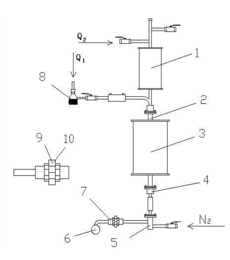
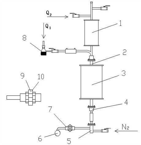
[0041] Embodiment 1: take by weighing 4# bituminous coal 40 + 0.5g (baked at 110°C for 3h) and put it into the spray bottle, weigh the total weight of the blow bottle (268.02g) and coal powder, record m 1 It is 308.02g. Turn on the air compressor, turn on the Q 1 , Q 2 Flow meter control valve, flow control is 1.0m 3 / h, 0.8m 3 / h. open N 2 device, flow control 2L / min. When blowing continuously for 8 minutes, cover the end of the dust collector with a rubber bag to collect gas and collect double samples. The injection time is set to 15min, and then turn off the N 2 device, Q 2 , Q 1 The flow meter controls the valve, weighs and records m 2 It is 289.64g. Remove the dust collector and ash collection tank in turn, collect unburned coal powder, and weigh m 3 It is 1.56g. Air blowing gas, control flow Q 1 2.0m 3 / h,Q 2 1.5m 3 / h, the time is 3 minutes. After the experiment is completed, turn off the air compressor. After the heating furnace cools down to below ...

Embodiment 2

[0057] Embodiment 2: take by weighing 2# anthracite 40g + 0.5 (baked at 105°C for 2h) and put it into the spray bottle, weigh the total weight of the spray bottle (268.02g) and coal powder, and record it as m 1 It is 308.37g. Open Q in sequence 1 , Q 2 Control valve, flow control is 0.8m 3 / h, 0.5m 3 / h, finally open N 2 device, flow control 2L / min. When blowing continuously for 5 minutes, start to collect gas and collect double samples. The injection time is set to 10min, and then turn off the N 2 device, Q 2 , Q 1 The flow meter controls the valve. Weigh and record m 2 It is 295.36g. Remove the dust collector and ash collection tank in turn, collect unburned coal powder, and weigh m 3 It is 1.13g. Air blowing gas, control flow Q 1 1.5m 3 / h,Q 2 1.0m 3 / h, the time is 2 minutes. After the experiment is completed, turn off the air compressor. After the furnace cools down to below 200°C (about 6h), turn off the main switch of the heating furnace, hot blast f...

Embodiment 3

[0070] Example 3: Weigh 40g of mixed coal (the ratio of 2 and 4# pulverized coal is 45:55) + 0.5 and put it into the blowing bottle, weigh the total weight of the blowing bottle (268.02g) and coal powder, and record it as m 1 It is 308.25g. Open Q in turn 1 , Q 2 Control valve, flow control is 0.9m 3 / h, 0.7m 3 / h, finally open N 2device, flow control 2L / min. When spraying continuously for 7 minutes, start to collect gas and collect double samples. The injection time is set to 12min, and then turn off the N 2 device, Q 2 , Q 1 The flow meter controls the valve. Weigh and record m 2 It is 294.18g. Remove the dust collector and ash collection tank in turn, collect unburned coal powder, and weigh m 3 It is 1.53g. Air blowing gas, control flow Q 1 1.8m 3 / h,Q 2 1.2m 3 / h, the time is 2.5 minutes. After the experiment is completed, turn off the air compressor. After the furnace cools down to below 250°C (about 5.5h), turn off the main switch of the heating furna...


PUM

PropertyMeasurementUnit
lengthaaaaaaaaaa
diameteraaaaaaaaaa
diameteraaaaaaaaaa

Abstract

The invention relates to a method and equipment for detecting burning rate of pulverized coal, belonging to the technical field of physical and chemical detection in metallurgical engineering. The method comprises the steps of: preparing coal samples, continuously blowing air, collecting unburned pulverized coal, collecting mixed gas, detecting by using a gas analyzer, burning in a muffle furnace and calculating burning rate. The equipment comprises a hot air furnace (1), a coal injection bottle (8), a burning furnace (3), an N2 gas source, a three-way ash collection groove (5), a gas collection bag (6) and a dust collector (7). The method and the equipment for detecting the burning rate of pulverized coal solve the problems that the burning rate of the equipment of the background technique is generally low and the unburned pulverized coal is difficult to collect, continuous injection is realized, and enough unburned pulverized coal (1g required by the national standard) and mixed gas can be collected. The accuracy of the detected burning rate of pulverized coal is high, the operation is simple and convenient, the repeatability is good, reference data for flammability of the kind of the injected pulverized coal can be provided for a blast furnace, and on the premise that the condition of the blast furnace is smooth, the benefit of coal injection is maximized by improving the burning rate of the pulverized coal.

Description

technical field [0001] The invention relates to a method and equipment for detecting the combustion rate of pulverized coal, belonging to the technical field of metallurgical engineering physical and chemical detection. Background technique [0002] Blast furnace pulverized coal injection is a technology developed in the 1980s, and it has become one of the main technical means adopted by blast furnaces in various countries to reduce the cost of pig iron and optimize the process structure. However, excessive injection of pulverized coal into the blast furnace will reduce the combustion rate of pulverized coal before the tuyere and increase the amount of unburned pulverized coal, which will bring a series of adverse effects to the normal smelting of the blast furnace. Therefore, the combustion rate of pulverized coal must be considered in the process of pulverized coal injection in the blast furnace, and the combustion rate should be increased as much as possible to maximize t...

Claims


Application Information

Patent Timeline
Patent Type & Authority Applications(China)
IPC IPC(8): G01N31/12
Inventor 吕庆刘然张淑会李福民孙艳芹冯帅梁坤峰
Owner NORTH CHINA UNIVERSITY OF SCIENCE AND TECHNOLOGY
Why Eureka
Try Eureka