Wide band sound absorption structure of film mechanical impedance combined with micropunched plate acoustic impedance

A technology of micro-perforated plate and mechanical impedance, which is applied in the direction of sound-generating devices and instruments, and can solve problems such as complex structure, large space occupation, and thickening

Inactive Publication Date: 2012-07-04
JIANGSU UNIV
View PDF5 Cites 17 Cited by
  • Summary
  • Abstract
  • Description
  • Claims
  • Application Information

AI Technical Summary

Problems solved by technology

The high sound absorption coefficient of the micro-perforated plate structure occurs near the cavity resonance, and the structural resonance frequency is mainly determined by the thickness of the back cavity. In order to obtain a good low-frequency sound absorption effect, the micro-perforated plate structure must be made very thick, which is It needs to occupy a lot of space, and it will encounter difficulties in actual engineering. Therefore, the low-frequency sound absorption performance of micro-perforated panels is not good, which has become a bottleneck restricting its engineering application.
[0003] At present, in order to improve the low-frequency sound-absorbing performance of the sound-absorbing structure, a composite structure combining micro-perforated plates and sound-absorbing materials appears, but this structure has the disadvantage of secondary pollution after using sound-absorbing materials. Good sound absorption at low frequencie

Method used


Image

  • Wide band sound absorption structure of film mechanical impedance combined with micropunched plate acoustic impedance
  • Wide band sound absorption structure of film mechanical impedance combined with micropunched plate acoustic impedance
  • Wide band sound absorption structure of film mechanical impedance combined with micropunched plate acoustic impedance

Examples


Embodiment Construction

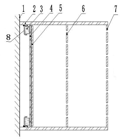
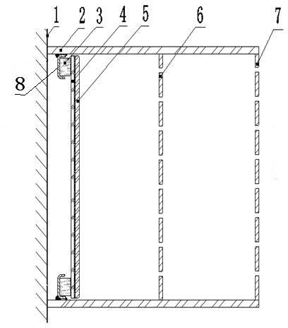
[0013] The following is attached figure 1 The present invention is described in further detail:

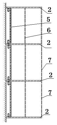
[0014] The present invention includes a bracket 2 fixedly installed on the wall 1. There are two brackets 2, and the two brackets 2 are installed up and down along the wall 1, and are all perpendicular to the wall 1. The bracket 2 is made of a metal plate with a thickness of 1 mm. . Connect the front micro-perforated plate 7 and the rear micro-perforated plate 6 between the two supports 2, the front micro-perforated plate 7 is installed on the front of the support 2, and the rear micro-perforated plate 6 is installed on the rear of the support 2, so that the front micro-perforated The plate 7 and the rear micro-perforated plate 6 are vertical to the support 2 respectively, a rectangular cavity is formed between the micro-perforated plate 7 and the rear micro-perforated plate 6, and another rectangular cavity is formed between the rear micro-perforated plate 6 and the wall 1. Loc...


PUM


Abstract

The invention discloses a wide band sound absorption structure of film mechanical impedance combined with micropunched plate acoustic impedance, which comprises an upper support and a lower support which are fixedly and perpendicularly connected with a wall. A front micropunched plate and a rear micropunched plate are fixedly and perpendicularly connected between the two supports. A rectangular cavity is formed respectively between the front micropunched plate and the rear micropunched plate and between the rear micropunched plate and the wall. In the rectangular cavity formed by the rear micropunched plate and the wall, the inner side faces of the two supports are respectively and fixedly connected with a groove structure with the front face of a groove mouth facing the rear micropunchedplate in a vertically symmetrical mode. An elastic ring is closely bonded in the groove mouth of the groove structure in an adhesive mode and bonded with a composite film in an adhesive mode, and thecomposite film is formed by evenly pasting an elastic film and a sound insulation film. A mechanical impedance unit formed by films is added in a rear cavity. The micropunched plate is combined with mechanical impedance of films, the micropunched plate structure is utilized to absorb sound energy at middle and high band, and mechanical impedance of films is utilized to absorb sound energy for lowfrequency. The broadband sound absorption structure has the advantage that sound absorption frequency band is wide.

Description

technical field [0001] The invention relates to sound-absorbing technology in the field of noise control, in particular to a sound-absorbing structure using a micro-perforated plate. Background technique [0002] Sound-absorbing technology is the core of noise control engineering. There are many sound-absorbing materials. Traditional porous fibrous materials have the disadvantage of secondary pollution. In 1975, Professor Ma Dayou published an article on "Theory and Design of Micro-perforated Plate Sound-absorbing Structure". Resonance absorbs sound energy. It is characterized by no need to add additional sound-absorbing materials. It is a green and environmentally friendly sound-absorbing structure, which has been applied in engineering. The high sound absorption coefficient of the micro-perforated plate structure occurs near the cavity resonance, and the structural resonance frequency is mainly determined by the thickness of the back cavity. In order to obtain a good low-...

Claims


Application Information

Patent Timeline
IPC IPC(8): G10K11/172G10K11/168
Inventor 赵晓丹丁瑞胡鹏
Owner JIANGSU UNIV
Why Eureka
Try Eureka