Common-rail fuel supply system of fuel cell or multi-fuel engine

A multi-fuel engine, common rail fuel technology, applied in fuel cells, fuel cell additives, charging systems, etc., can solve the problem that the fuel cell system or fuel cell engine fuel supply cannot be accurately controlled, the fuel cell engine system is complex, The system has problems such as poor dynamic response performance, which can improve the control accuracy and dynamic response speed, solve the pressure balance problem, and have a simple structure.

Active Publication Date: 2012-07-04
SAIC MOTOR
View PDF3 Cites 14 Cited by
  • Summary
  • Abstract
  • Description
  • Claims
  • Application Information

AI Technical Summary

Problems solved by technology

[0004] In addition, the fuel (hydrogen) supply system or input circuit of fuel cell systems and fuel cell engines in the past is usually composed of components such as decompression buffer valves, solenoid valves, proportional control valves, and hydrogen return pumps. These components are mostly used in the chemical industry. , has defects such as high cost, limited temperature range, and slow response speed. The fuel cell system or fuel cell engine formed is not suitable for equipment or occasions with high dynamic response requirements, such as automotive applications.
[0005] Furthermore, due to the limitations of the design of the fuel supply system and components, the system cannot accurately control the fuel supply of the fuel cell system or the fuel cell engine
[0006] To sum up the defects mentioned above, when the existing fuel supply system is applied in some fields (for example, on automobiles), the fuel cell system or fuel cell engine system constituted is complicated, has low efficiency, and poor control accuracy, and it is difficult to ensure The pressure balance under environmental conditions will affect the service life of the system. More importantly, the dynamic response performance of the system is not good, and it cannot surpass the traditional engine to meet the actual application requirements.

Method used


Image

  • Common-rail fuel supply system of fuel cell or multi-fuel engine
  • Common-rail fuel supply system of fuel cell or multi-fuel engine
  • Common-rail fuel supply system of fuel cell or multi-fuel engine

Examples


Embodiment Construction

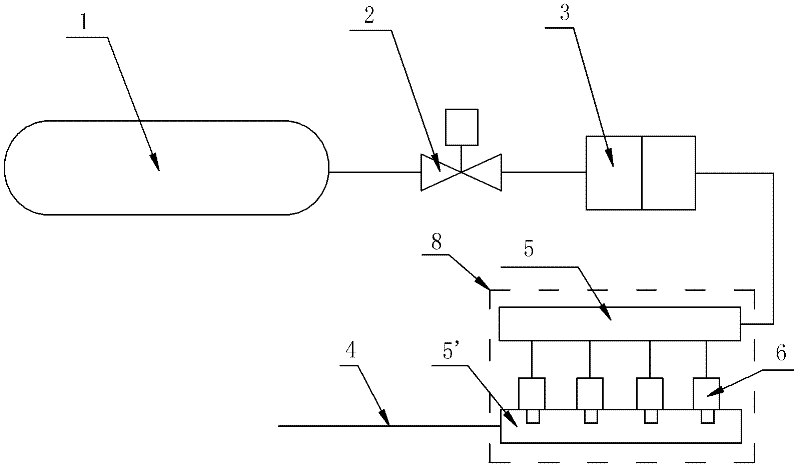
[0023] The first implementation of the present invention is as figure 1 As shown, the fuel source 1 is made of high-pressure hydrogen cylinders, which include necessary components such as buffer valves and overflow valves. Of course, in the present invention, it is not limited to the use of hydrogen fuel, and it can also be CNG (compressed natural gas), LPG (liquefied petroleum gas), etc. gas), gasoline, ethanol gasoline and other available fuels. The high-pressure hydrogen bottle 1 is connected with a fuel delivery pipeline 4, which can provide fuel for a fuel cell, a fuel cell engine, or a multi-fuel engine. A valve 2, a pressure regulator 3 and a common rail injection device 8 are sequentially connected in series in the fuel delivery pipeline 4, wherein the common rail injection device 8 includes two fuel rails 5, 5' at the front and rear, and two fuel rails connected in parallel. Between a plurality of injectors 6, the input end of each injector 6 is connected with the fr...


PUM


Abstract

The invention discloses a common-rail fuel supply system of fuel cells or multi-fuel engines, which comprises a fuel source and a fuel conveyer pipe; a valve, a pressure regulator, and a common-rail injection apparatus are serially connected on the fuel conveyer pipe; the common-rail injection apparatus comprises a front and a back fuel rails, and a plurality of injectors parallelly connected between the two fuel rails; input ends of the injectors are all connected with the front fuel rail, and injection ends of the injectors are all connected with the back fuel rail. The invention brings into full play of the advantages of a fuel cell system, effectively solves the problem of pressure balance of a fuel cell electric pile, and greatly improves the service life of the fuel cell electric pile; the invention precisely and rapidly controls the fuel supply amount, and increases the control precision and the dynamic response speed; the invention realizes a simple structure, low cost, a long service life, and long-lasting stable and reliable operation of a fuel cell system or a fuel cell engine system, is applicable to transportation means such as automobile and the like, and meets the special requirements of zero discharge, large power, and fast dynamic response.

Description

technical field [0001] The invention relates to a fuel supply system for a fuel cell, in particular to a common rail fuel supply system for a fuel cell or a fuel cell engine or a multi-fuel engine. Background technique [0002] In the field of new energy technology, the core part of fuel cell system and fuel cell engine technology is the fuel cell stack. The fuel cell system is composed of a fuel cell stack, equipped with a fuel supply system, an air or oxygen supply system, a cooling water system, and a control system; a fuel cell engine is a fuel cell system applied to transportation equipment. [0003] Large fuel cell systems typically operate at high pressure or pressurization. The reason for operating fuel cells and fuel cell engine systems at higher pressures is that the exchange current density of fuel cell stacks increases under high pressure, which significantly increases the open circuit voltage of the battery and ultimately increases the output power of the fuel ...

Claims


Application Information

Patent Timeline
Patent Type & Authority Applications(China)
IPC IPC(8): H01M8/04F02M43/00H01M8/04082H01M8/04089
CPCY02E60/50
Inventor 卢冶干频刘奋章道彪倪天鹿
Owner SAIC MOTOR
Why Eureka
Try Eureka