
Magnetic fluid power generation device

A magnetic fluid power generation and power generation device technology, which is applied to generators/motors, generators that convert kinetic energy into electrical energy, electrical components, etc., can solve the problems of low utilization rate of plasma gas, shortened motor life, and high price.

Inactive Publication Date: 2012-07-04
曾令伦
View PDF6 Cites 15 Cited by
  • Summary
  • Abstract
  • Description
  • Claims
  • Application Information

AI Technical Summary

Problems solved by technology

The magnetic fluid generator in the experimental stage, by heating the working fluid gas and adding ionized seeds such as potassium and cesium, makes it have a certain conductivity, so that power generation can be carried out, and then combined with the steam power station system, the total efficiency can reach 52% or even Higher, but the gas conductivity is not high enough, and it is extremely difficult to further increase it. Superconducting magnets must be used to obtain strong magnetic induction, which is very expensive; ionized seeds, cinders, dust, etc. in the gas will easily short-circuit the electrodes of the motor channel and corrode. Thereby shortening the life of the motor; the utilization rate of plasma gas is not high, only electrons are carriers, and positive ions are not carriers
Widely used solar cells are based on the principle of photoelectric conversion, using semiconductor materials to absorb sunlight to generate electricity, but the current photoelectric conversion efficiency is not very high, the highest is only about 30%, the solar thermal energy has not been fully utilized, and the production cost is high

Method used


Image

  • Magnetic fluid power generation device
  • Magnetic fluid power generation device
  • Magnetic fluid power generation device

Examples


Embodiment Construction

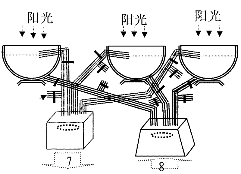
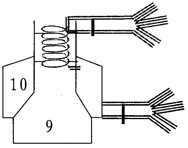
[0143] Embodiments of the present invention are such that the power generation device mainly consists of solar reflectors, air intake pipes (such as figure 2 ), jet chamber 43, ionization chamber 44, power generation channel 45, recovery chamber 47, exhaust pipe, permanent magnet (as Figure 25 ), transmission system (such as Figure 22 ), battery pack 87, additional fossil fuel combustion chamber (such as image 3 ). It is characterized in that the ionization chamber is provided with 2 pairs of positive and negative reverse high-voltage discharge rods 54, 55, 56, 57, the outlet end of the power generation channel is provided with an inwardly curved arc-shaped collection baffle 46, and the reflector is composed of a hemispherical concave mirror and a small cylinder Composition, equipped with tracking ray automatic steering device (such as Figure 4 ), the jet chamber is equipped with an intake pump and a tourmaline net (such as Figure 13 ), the recovery chamber is provid...


PUM


Abstract

The invention relates to a magnetic fluid power generation device, which is composed of a solar reflector, an air inlet pipe, an air injection chamber, an ionization chamber, a power generation channel, a recovery chamber, an exhaust pipe, a permanent magnet, a power transmission system and a storage battery pack, wherein a fossil fuel combustion chamber is added additionally. The ionization chamber is provided with two pairs of positive and negative reverse high-voltage discharging rods, the power generation channel is provided with a collection baffle, the reflector is composed of a hemispheric concave mirror and a small cylinder and provided with an automatic steering device for tracking light, the air injection chamber is provided with an air inlet pump and a tourmaline net, and the recovery chamber is provided with an exhaust pump. Working medium xenon absorbs heat in the reflector to rise to a high temperature to be input in the air inlet pipe, is accelerated through the air injection chamber, rubs with the tourmaline net to be ionized, and is sprayed in the ionization chamber to encounter a cross strong electric field to generate electric corona, all of the gas is almost ionized, generated plasma gas enters the power generation channel and is affected by Lorentz force to have deflection, positive and negative charged particles are respectively concentrated on the collection baffle and a negative plate to form a positive pole and a negative pole of a generator, electric power is led out, and rated alternating current is output after voltage stabilization and inversion. Two poles of the generator are in parallel connection with the storage battery pack to be charged or discharged mutually. The magnetic fluid power generation device has the advantages of utilizing light energy and heat energy, converting the light energy and the heat energy into electric energy, and obtaining high power generation efficiency.

Description

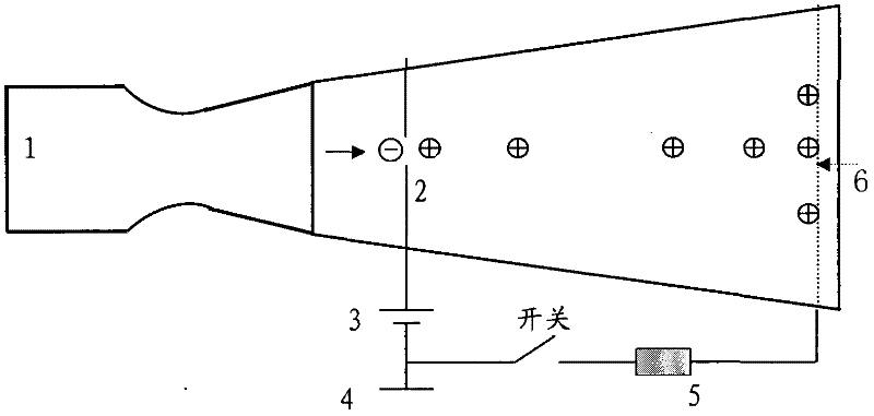
technical field [0001] The invention relates to a new type of magnetic fluid power generation device, which mainly utilizes solar energy to heat ionized working gas, implement corona discharge to generate plasma gas, and then generate electricity. Background technique [0002] At present, electric gas generators are used in some low-power places, such as the power supply of aerospace vehicle rocket engines, electrostatic spraying, electrostatic dust removal, etc., but its utilization rate of plasma gas is not high, and only the positive ions in it have made significant contributions to power generation. Contribution, electrons are not carriers, only positive ions are carriers, and the energy conversion rate is up to 50% (such as figure 1 ). The magnetic fluid generator in the experimental stage, by heating the working fluid gas and adding ionized seeds such as potassium and cesium, makes it have a certain conductivity, so that power generation can be carried out, and then c...

Claims


Application Information

Patent Timeline
Patent Type & Authority Applications(China)
IPC IPC(8): H02N3/00
Inventor 曾令伦
Owner 曾令伦
Learn More