Heavy gear transmission vertical broaching machine tool

A gear transmission, vertical technology, applied in the direction of belt/chain/gear, gear teeth, mechanical equipment, etc., can solve the problems of unsuitable heavy and large workpiece, accurately determine the source of system failure, and limit the processing range, and achieve a compact structure. , The effect of shortening maintenance time and high bearing capacity

Inactive Publication Date: 2012-07-11
CHAGYI LIHUI BROACHING MACHINE MAFACTURE
View PDF7 Cites 2 Cited by
  • Summary
  • Abstract
  • Description
  • Claims
  • Application Information

AI Technical Summary

Problems solved by technology

[0002] The vertical broaching machine in the prior art usually includes a base, on which a bed is arranged, and a main slide that can move up and down is arranged on the bed, and also includes a hydraulic drive device for driving the main slide. The broach on the main slide completes the processing of the workpiece. Since the hydraulic drive device is a complex electromechanical-hydraulic integrated system, once the system fails, it is often difficult to accurately determine the source of the system failure in a short period of time. Can rely on experience for analysis, resulting in slow maintenance and low work efficiency; and the vertical broaching machine with this structure is only suitable for processing light and small workpieces, not suitable for heavy and large workpieces, and its processing range is limited

Method used


Image

  • Heavy gear transmission vertical broaching machine tool
  • Heavy gear transmission vertical broaching machine tool
  • Heavy gear transmission vertical broaching machine tool

Examples


Embodiment Construction

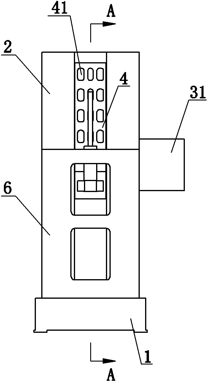
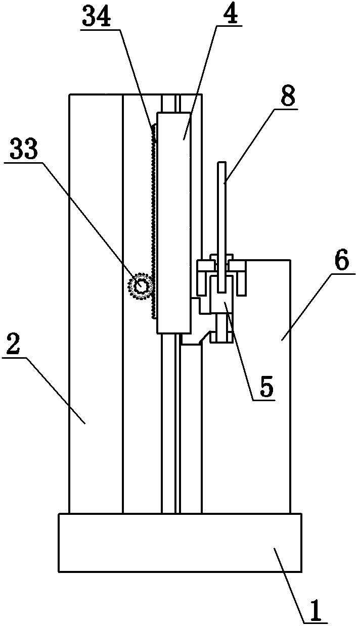
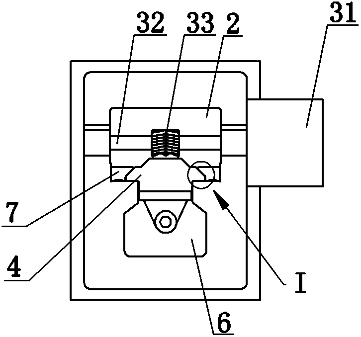
[0018] Such as figure 1 , figure 2 and image 3 Commonly shown is a structural schematic diagram of a heavy-duty gear-driven vertical broaching machine tool, which includes a base 1 and a bed 2 fixed on the base 1, and the bed 2 is provided with guide rails 7 extending vertically In the guide rail 7, there is a main sliding plate 4 which is adapted to it and can slide linearly back and forth along its extension direction. The main sliding plate 4 is driven by a power device, and the power device described here includes a motor 31, The drive shaft 32 connected to the output end of the motor 31, the drive gear 33 fixed on the drive shaft 32 and the drive rack 34 fixed on the main slide plate 4, the drive gear 33 and the drive rack 34 The drive gear 33 is preferably a herringbone gear, and the drive rack 34 is a herringbone rack that is compatible with the drive gear 33; The clamping device 5 of 8 is also provided with a workbench 6 for supporting the workpiece on the base 1,...


PUM


Abstract

The invention discloses a heavy gear transmission vertical broaching machine tool. The heavy gear transmission vertical broaching machine tool comprises a base and a machine tool body, wherein the machine tool body is fixed on the base; a guide rail extending in the vertical direction is arranged on the machine tool body; a main slide carriage driven by a power device and linearly moving in a reciprocating way is arranged within the guide rail; the power device comprises an electric motor and a driving shaft; the driving shaft is connected to an output end of the electric motor; a driving gear is arranged on the driving shaft; a driving rack adaptive to the driving gear is fixed on the main slide carriage; a clamping device for fixing a broaching tool is arranged on the main slide carriage; the heavy gear transmission vertical broaching machine tool also comprises a workbench arranged on the base; and a fixing device for fixing a workpiece is arranged on the workbench. The heavy gear transmission vertical broaching machine tool disclosed by the invention has the advantages of simple transmission mode and convenience for mounting and is very suitable for broaching heavy and large-sized workpieces; the bearing capacity of the broaching machine tool can be effectively enhanced so that the transmission is stable and the error generated in the machining process is largely reduced; and the fault source can be accurately figured out in time after the fault occurs so that the maintenance time is reduced.

Description

technical field [0001] The invention relates to the technical field of vertical broaching machines, in particular to a heavy-duty gear-driven vertical broaching machine tool. Background technique [0002] The vertical broaching machine in the prior art usually includes a base, on which a bed is arranged, and a main slide that can move up and down is arranged on the bed, and also includes a hydraulic drive device for driving the main slide. The broach on the main slide completes the processing of the workpiece. Since the hydraulic drive device is a complex electromechanical-hydraulic integrated system, once the system fails, it is often difficult to accurately determine the source of the system failure in a short period of time. Can rely on experience for analysis, resulting in slow maintenance and low work efficiency; and the vertical broaching machine with this structure is only suitable for processing light and small workpieces, not suitable for heavy and large workpieces,...

Claims


Application Information

Patent Timeline
IPC IPC(8): B23F5/28B23Q1/01B23Q1/25B23Q5/34
Inventor 田立辉王永利李勇
Owner CHAGYI LIHUI BROACHING MACHINE MAFACTURE
Why Eureka
Try Eureka