Multifunctional substrate polishing and burnishing device and polishing and burnishing method thereof
A multi-functional, substrate-based technology, applied in the direction of grinding devices, grinding drive devices, grinding/polishing equipment, etc., can solve the problems of not being applicable to different usage requirements of various substrates, reduce production costs and improve product quality , the effect of improving efficiency
- Summary
- Abstract
- Description
- Claims
- Application Information
AI Technical Summary
Problems solved by technology
Method used
Image

Examples
Embodiment 1
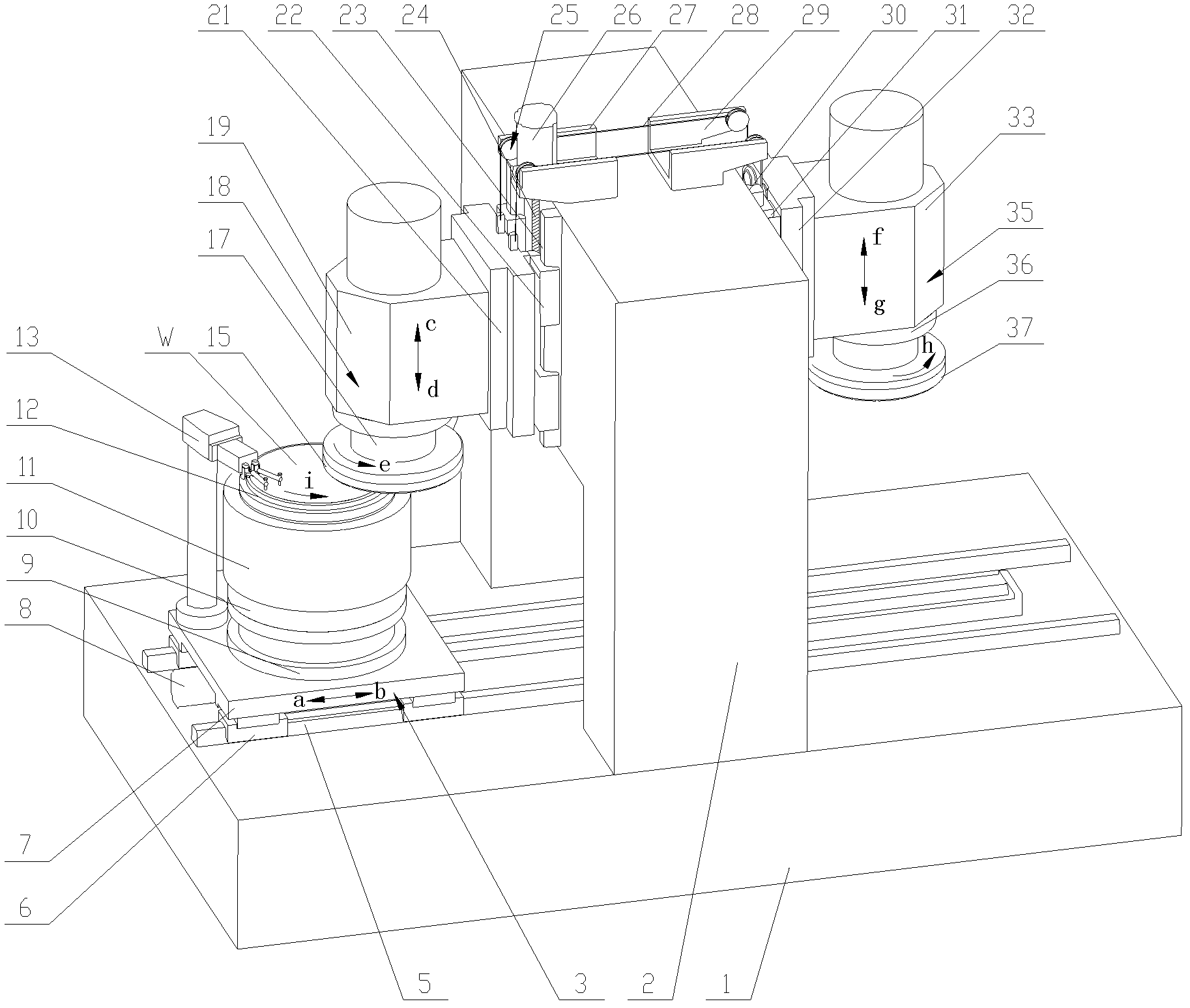
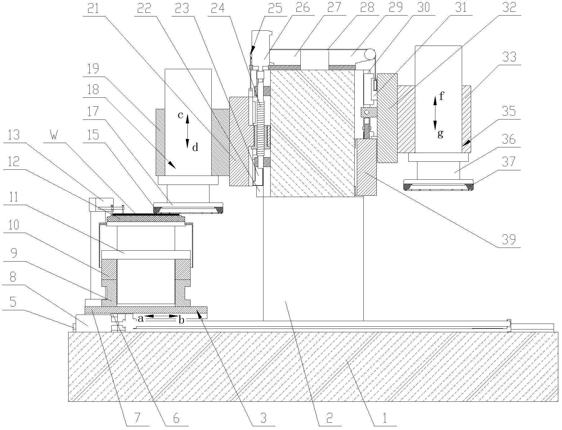
[0018] Embodiment 1, using the axial incision grinding and polishing method to process the disc-shaped substrate, see Figure 4 . The processed substrate W is placed on the suction cup 12, and the worktable 3 is driven by the feed mechanism 8 to move forward in the direction of the arrow b in the horizontal direction to the bottom of the grinding spindle unit 18, and the center of the wafer-shaped substrate W is Located at the outer edge of the grinding wheel 15, the workbench 3 is kept fixed in the horizontal direction. Driven by the workpiece spindle 11, the substrate W is rotated along the chuck rotation direction i. The grinding wheel 15 of the grinding spindle unit 18 rotates along the grinding wheel rotation direction 1e; at the same time, the grinding spindle unit 18 feeds along the d direction of the grinding feed direction when the motor 26 rotates forward, and as a result, the The substrate W is subjected to conventional fixed-pass grinding. Or the grinding spindl...
Embodiment 2
[0019] Embodiment two, adopting radial cut-in type grinding and polishing method to process square chip substrate, see Figure 4 . The grinding wheel 15 of the grinding spindle unit 18 rotates in the direction e. Simultaneously, the grinding spindle unit 18 feeds downwards along the d of the grinding feed direction when the motor 26 rotates forward, keeps the grinding spindle unit 18 fixed in position on the grinding feed direction, and the workbench 3 is positioned on the feed mechanism 8 Driven by the driving force, move toward b in the horizontal direction until the edge of the substrate W touches the outer edge of the grinding wheel 15 and start grinding, and continue to move in the direction b in the horizontal direction until the edge of the substrate W breaks away from the outer edge of the grinding wheel 15 to end the grinding. Driven by the feed mechanism 8, the workbench 3 moves horizontally toward the direction a and returns to the initial grinding position. The th...
Embodiment 3
[0020] Embodiment three, adopt the edge grinding and polishing method to process, see Figure 5. When a small-diameter grinding wheel or polishing wheel 40 is used, edge-reserving grinding or edge-reserving polishing can be realized, and the diameter of the small-diameter grinding wheel or polishing wheel 40 is slightly smaller than the radius of the substrate W. The substrate W to be processed is placed on the suction cup 12, and the worktable 3 is moved forward in the horizontal direction toward b to the bottom of the grinding spindle unit 18 under the drive of the feed mechanism 8, so that the outer edge of the grinding wheel 15 passes through the circle. At the center of the sheet-like substrate W, the position of the holding table 3 in the horizontal direction is fixed. Driven by the workpiece main motor shaft 11, the substrate W is rotated along the i direction of the chuck rotation direction. The grinding wheel 15 of the grinding spindle unit 18 is so as to rotate alo...
PUM
 Abstract
Description
Claims
Application Information
 - Generate Ideas
- Intellectual Property
- Life Sciences
- Materials
- Tech Scout
- Unparalleled Data Quality
- Higher Quality Content
- 60% Fewer Hallucinations
Browse by: Latest US Patents, China's latest patents, Technical Efficacy Thesaurus, Application Domain, Technology Topic, Popular Technical Reports.
© 2025 PatSnap. All rights reserved.Legal|Privacy policy|Modern Slavery Act Transparency Statement|Sitemap|About US| Contact US: help@patsnap.com