Antifoaming gradient porous structure in plasma-facing material

A technology of plasma and gradient porosity, which is applied to the structure of plasma materials and the field of gradient porous structure, which can solve the problems of shortening the life of plasma materials, affecting plasma stability, and surface peeling, so as to improve the service life and avoid breakdown. Foam, good binding effect

Inactive Publication Date: 2012-07-11
BEIHANG UNIV
View PDF7 Cites 5 Cited by
  • Summary
  • Abstract
  • Description
  • Claims
  • Application Information

AI Technical Summary

Problems solved by technology

However, the currently used tungsten material will produce bubbles on the surface under long-term irradiation of deuterium and helium plasma, which is caused by the accumulation of hydrogen, helium and its isotopes below the surface.
Severe foaming will affect the service condition of the plasma-facing material, cause surface peeling, seriously affect the stability of the plasma, and shorten the life of the plasma-facing material itself

Method used


Image

  • Antifoaming gradient porous structure in plasma-facing material
  • Antifoaming gradient porous structure in plasma-facing material
  • Antifoaming gradient porous structure in plasma-facing material

Examples


Embodiment 1

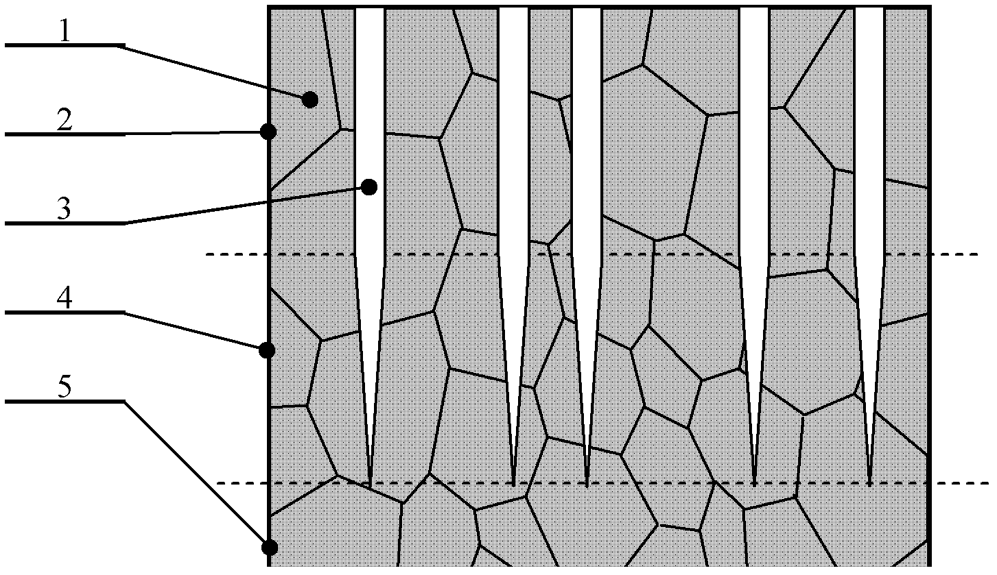
[0019] Such as figure 1 As shown, this is a form of gradient porous structure of tungsten-based plasma material, which can be prepared by conventional powder sintering method. This form of porosity is characterized by irregularities. The gradient porous structure is composed of three layers in the thickness direction according to the change of porosity, such as figure 1 , the most surface part is the surface porous layer 2, the part closely connected with the surface porous layer 2 is the gradient transition layer 4, and the bottom part closely connected with the gradient transition layer 4 is the matrix 5;

[0020] The thickness of the superficial porous layer 2 is 3 microns. Wherein there is a large amount of pores 3, and its porosity is 35%, and all pores 3 are all connected with the surface, and there is horizontal interpenetration, and the lateral particle diameter of the solid tungsten 1 that forms the network frame is 2 microns; The described pores 3 consists of a ne...

Embodiment 2

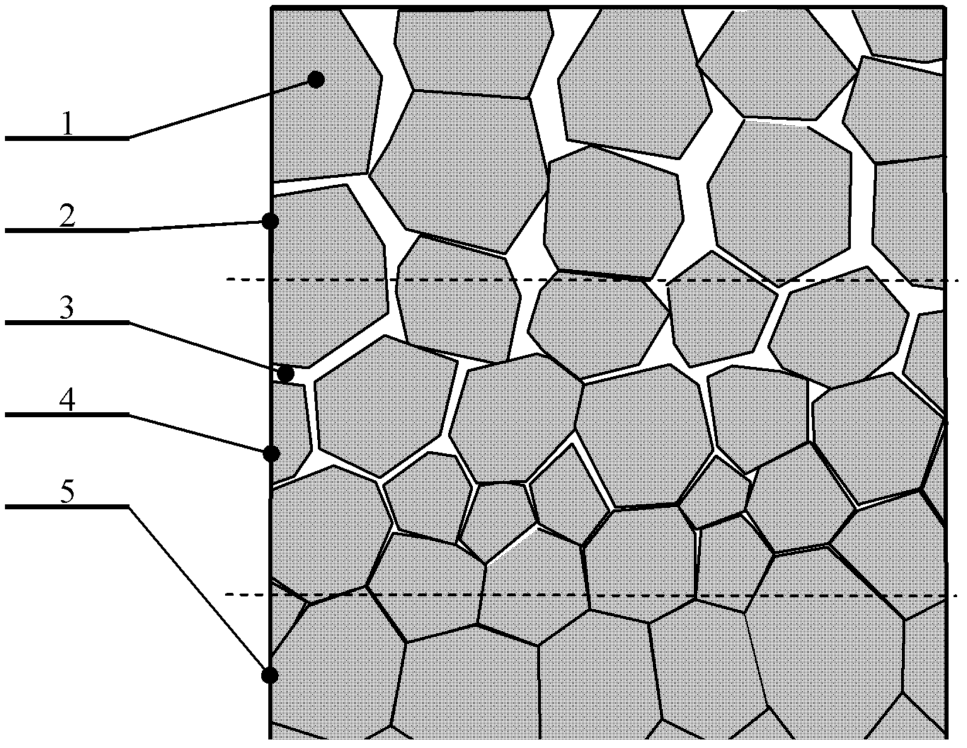
[0024] This is another form of gradient porous structure with tungsten substrates facing plasmonic materials, such as figure 2 , can be prepared by conventional template electrochemical etching method. The characteristic of this form of pores is that the pores are basically perpendicular to the surface, which is relatively regular and smooth. It is also composed of three layers in the thickness direction according to the change of porosity: the most surface part is the surface porous layer 2, the part closely connected with the surface porous layer 2 is the gradient transition layer 4, and the bottom part is the gradient transition layer 4. The closely connected part of the transition layer 4 is the matrix 5;

[0025] The thickness of the superficial porous layer 2 is 8 microns. There are a large number of pores 3, the porosity of which is 20%, and all pores 3 are connected to the surface, and the transverse grain size of the network frame composed of solid tungsten 1 is 1....


PUM

PropertyMeasurementUnit
Thicknessaaaaaaaaaa
Thicknessaaaaaaaaaa
Thicknessaaaaaaaaaa

Abstract

The invention belongs to the field of nuclear fusion energy application, and discloses an antifoaming gradient porous structure in a plasma-facing material. According to the variation of the porosity, on a thickness direction, the tungsten-based plasma-facing material with the gradient porous structure is composed of three layers of components, which are a surface porous layer, a gradient transition layer, and a substrate. The porosity of the gradient transition layer is gradually reduced from the porosity at the place of the surface porous layer along a depth direction, such that a gradient change is formed. Finally, the porosity of the gradient transition layer is the same with that of the substrate. According to the invention, with the pores communicating with the surface, hydrogen andhelium entering the plasma-facing material are delivered back to the surface, such that the formation of inner foam in the plasma-facing material is avoided, and a phenomenon of foaming is eliminated.

Description

technical field [0001] The invention belongs to the application field of nuclear fusion energy, and in particular relates to a gradient porous structure facing the anti-foaming in the plasma material, which is suitable for the plasma irradiation environment with hydrogen, helium and its isotopes, as a nuclear fusion device The structure of the mid-face plasmonic material. Background technique [0002] With the increasing consumption of existing fossil energy reserves, there are safety and environmental problems in the form of nuclear fission energy; while nuclear fusion energy is not only extremely rich in resource reserves, but also has no radioactivity compared with fission and is very safe. Therefore, nuclear fusion energy may become The ultimate energy source for human beings. [0003] In a nuclear fusion device, the materials facing the plasma (including the first wall and divertor materials) have to withstand the test of harsh environments such as high thermal shock, ...

Claims


Application Information

Patent Timeline
IPC IPC(8): C22C27/04C22C1/08C22C1/04B22F7/02
Inventor 吕广宏程龙王波张颖
Owner BEIHANG UNIV
Why Eureka
Try Eureka