
Metal plastic coated mixing valve body and manufacturing method thereof

A manufacturing method and technology of water mixing valves, applied in valve details, multi-way valves, valve devices, etc., can solve problems such as environmental damage, high labor intensity, complex processing technology, etc., achieve strong anti-leakage ability and improve production efficiency , cost reduction effect

Inactive Publication Date: 2012-07-11
叶建科
View PDF0 Cites 2 Cited by
  • Summary
  • Abstract
  • Description
  • Claims
  • Application Information

AI Technical Summary

Problems solved by technology

[0002] Existing water mixing valve bodies are all made of metal die-casting or plastic injection molding. Due to the cavity inside, it causes problems such as difficult core pulling and demoulding for special-shaped products.
Therefore, they are all divided into several parts for processing and then assembled. The labor intensity is high and the processing technology is complicated; whether welding or screw fitting is used during assembly, certain traces or gaps will be produced, which will affect the appearance. Therefore, the high-end market has been looking for The ideal product to address this drawback
At the same time, the cost of all metal materials is quite high, and the surface needs to be polished and electroplated. Plastic instead of strength is not ideal

Method used


Image

  • Metal plastic coated mixing valve body and manufacturing method thereof
  • Metal plastic coated mixing valve body and manufacturing method thereof
  • Metal plastic coated mixing valve body and manufacturing method thereof

Examples


Embodiment Construction

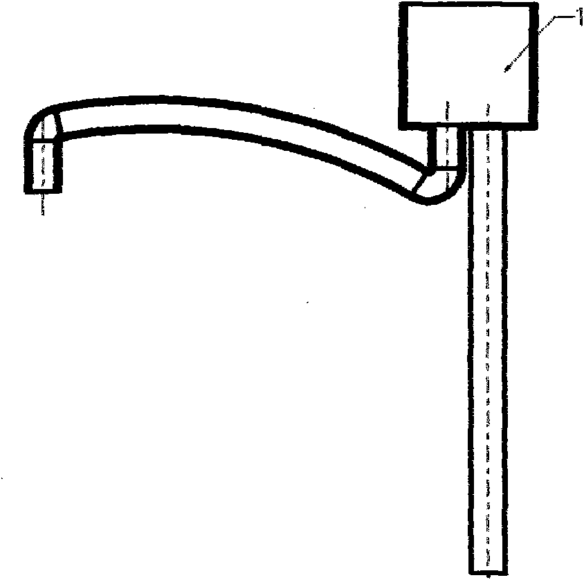
[0013] The specific manufacturing method of the present invention will be further described with reference to the accompanying drawings.

[0014] In order to achieve the purpose of the present invention, a metal-coated plastic mixing valve body provided by the present invention improves the single material of the product. In order to meet the standard requirements for internal strength and corrosion resistance, the internal material is made of stainless steel or copper plates and pipes; for To meet the installation and use requirements of the product, the surface is wrapped with plastic to make the product meet the ideal requirements.

[0015] A method for manufacturing a metal-coated plastic mixing valve body according to the present invention, the specific implementation method is divided into the following steps:

[0016] ① Use stainless steel or copper material to stretch out the water mixing valve cavity 1, punch out the water inlet and outlet holes on the cavity, and set...


PUM


Abstract

The invention discloses a metal plastic coated mixing valve body and a manufacturing method thereof. An internal cavity made of stainless steel or copper is arranged inside the valve body and the surface of the valve body is coated with plastic so that the valve body looks the same in appearance with an ideal valve. The manufacturing method includes the steps of: (1) blanking and punching a stainless steel plate or a copper plate and molding a cavity of the mixing valve body through drawing process for standby use; (2) blanking a stainless steel pipe or a copper pipe and bending the pipe to form a water inlet and outlet pipeline for standby use; (3) taking the semi-finished products from step (2) and step (2), welding the two semi-finished products to form the internal cavity of the mixing valve body for standby use; (4) finally, putting the welded internal cavity obtained from step (3) in an injection mold for coating plastic. The mixing valve body can meet the desired requirements without polishing or electrofacing the surface. The mixing valve body and the manufacturing method have the beneficial effects that: the disadvantages of the prior art are solved; under the precondition that the mixing valve body has the same compression strength and service life with the prior art, the manufacturing method can greatly reduce the production cost, improves the production efficiency and is more environment-friendly.

Description

(1) Technical field [0001] The invention relates to a water mixing valve body, which is a metal-plastic-coated water mixing valve body, which can effectively reduce the cost and solve the difficulty of pulling out the core of the special-shaped valve body, and completely eliminate the problems of traces and gaps affecting the appearance of each component assembly. (2) Background technology [0002] Existing water mixing valve bodies are all made of metal die-casting or plastic injection molding. Due to the cavity inside, it causes problems such as difficult core pulling and demoulding for special-shaped products. Therefore, they are all divided into several parts for processing and then assembled. The labor intensity is high and the processing technology is complicated; whether welding or screw fitting is used during assembly, certain traces or gaps will be produced, which will affect the appearance. Therefore, the high-end market has been looking for The ideal product to ad...

Claims


Application Information

Patent Timeline
Patent Type & Authority Applications(China)
IPC IPC(8): F16K27/00F16K11/00
Inventor 叶建科
Owner 叶建科
Learn More