Groove type condensation solar heat collecting tube with compensation sealing structure and assembling process of groove type condensation solar heat collecting tube

A technology of concentrating solar energy and sealing structure, which is applied in the field of solar thermal utilization, which can solve the problems of high welding quality requirements, expansion stress and welding stress, and difficulty in non-destructive testing at transitional parts, so as to facilitate weld surface detection, welding Few defects, prevent heat loss effect

Active Publication Date: 2013-08-21
溧阳常大技术转移中心有限公司
View PDF8 Cites 1 Cited by
  • Summary
  • Abstract
  • Description
  • Claims
  • Application Information

AI Technical Summary

Problems solved by technology

The Kovar ring is made of expensive Kovar alloy (4J29) to ensure the sealing, but in the process of processing the Kovar ring, there will be margins and scraps, which will cause waste of expensive Kovar alloy and further increase the cost; and the transition part is welded High quality requirements and difficult non-destructive testing
[0004] It can be seen that the sealing method of the metal tube and the glass tube of the solar collector tube adopts the metal bellows to slow down the longitudinal expansion stress, the Kovar alloy transition and welding with the glass tube, but there is expansion stress and welding stress. During use, prone to stress failure

Method used


Image

  • Groove type condensation solar heat collecting tube with compensation sealing structure and assembling process of groove type condensation solar heat collecting tube

Examples


Embodiment Construction

[0041] The present invention is described in further detail now in conjunction with accompanying drawing. These drawings are all simplified schematic diagrams, which only illustrate the basic structure of the present invention in a schematic manner, so they only show the configurations related to the present invention.

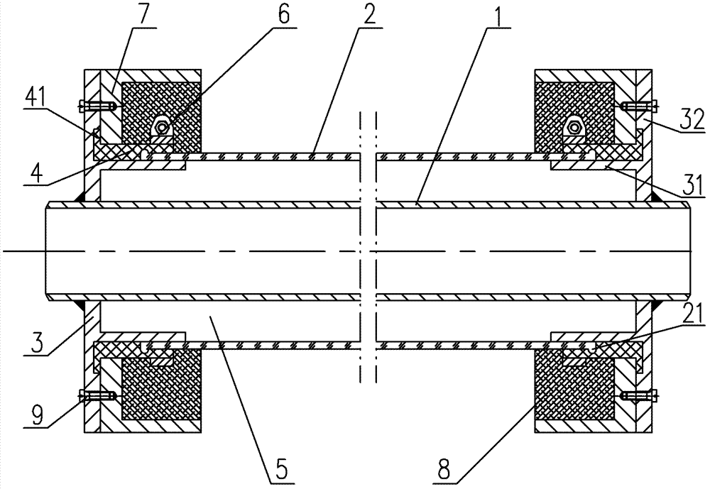
[0042] Such as figure 1 The best embodiment of the trough-type concentrating solar heat collector tube with compensating sealing structure of the present invention shown, it has coating stainless steel tube 1, coating stainless steel tube 1 outer jacket is equipped with coating borosilicate glass tube 2, coating Both ends of the stainless steel tube 1 are fitted with a stainless steel head 3, and the outer wall of the coated stainless steel tube 1 is in sealing connection with the stainless steel head 3; the coated silicon borosilicate glass tube 2 is in sliding connection with the stainless steel head 3; High-temperature silicone rubber compensation sleeve 4...


PUM

PropertyMeasurementUnit
lengthaaaaaaaaaa

Abstract

The invention belongs to the technical field of solar thermal utilization, and particularly discloses a groove type condensation solar heat collecting tube with a compensation sealing structure. The groove type condensation solar heat collecting tube is provided with a coated stainless steel tube, a coated borosilicate glass tube is sleeved on the outside of the coated stainless steel tube, stainless steel seal heads are sleeved at both ends of the coated stainless steel tube, and the outer wall of the coated stainless steel tube is hermetically connected with the stainless steel seal heads; the coated borosilicate glass tube is slidably connected with the stainless steel seal heads; high-temperature-resistant silicon rubber compensation sleeves are sleeved on the stainless steel seal heads, and two ends of each high-temperature-resistant silicon rubber compensation sleeve are respectively hermetically connected with the coated borosilicate glass tube and the corresponding stainless steel seal head; and heat-insulation vacuum chambers are disposed among the coated stainless steel tube, the coated borosilicate glass tube and the stainless steel seal heads. The heat collecting tube is provided with the high-temperature-resistant silicon rubber compensation sleeves with cheap prices, stress destruction can be avoided, components of the heat collecting tube are welded and hermetically sealed, and accordingly the groove type condensation solar heat collecting tube is high in reliability and structural tension resistance and fine in heat-insulation performance. In addition, welding operation is seldom carried out in assembling process, yield of finished products is high, the process is simple, and labor cost is low.

Description

technical field [0001] The invention belongs to the technical field of solar light and heat utilization, in particular to a trough-type concentrating solar heat collection tube with a compensation sealing structure and an assembly process thereof. Background technique [0002] The trough concentrated solar thermal power generation system mainly consists of a trough concentrated solar heat collection system, a heat transfer and exchange system, a power generation system, a heat storage system and a heat supplement system, among which the trough concentrated solar heat collection system is the core of the power generation system. key core part. The trough concentrated solar heat collection system is mainly composed of a parabolic reflector, a high temperature vacuum heat collection tube, a solar tracking and hydraulic drive system, a support mechanism and a high temperature medium transmission system. The light reflected by the parabolic reflector converges to a line on which...

Claims


Application Information

Patent Timeline
Patent Type & Authority Patents(China)
IPC IPC(8): F24J2/46
CPCY02E10/40Y02E10/44F24J2/055F24J2002/4681F24S10/45F24S2025/6013
Inventor 陶国良
Owner 溧阳常大技术转移中心有限公司
Why Eureka
Try Eureka