Light path of ultraviolet visible spectrophotometer

A spectrophotometer, ultraviolet technology, applied in the direction of spectrophotometry/spectrophotometry/monochromator, optical radiation measurement, measurement device, etc. Sample use cost, high optical path energy, and low energy loss

Inactive Publication Date: 2012-07-11
SHANGHAI METASH INSTR
View PDF3 Cites 3 Cited by
  • Summary
  • Abstract
  • Description
  • Claims
  • Application Information

AI Technical Summary

Problems solved by technology

The optical path design of the traditional UV-visible spectrophotometer makes the optical path of the monochromator and the sample chamber long, and the energy loss is large, resulting in low energy when testing the sample, and the test of high-concentration substances is limited; the optical path design of the traditional UV-visible spectrophotometer It makes it bulky, which is not conducive to normal placement in crowded laboratories; the optical path design of the traditional UV-Vis spectrophotometer makes the light spot passing through the sample longer, and the amount of sample required for the test is large, but nucleic acid samples are very precious, so it is not suitable A lot of waste; the optical path design of the traditional UV-visible spectrophotometer makes the optical path of the sample chamber longer, and the insertion and removal of the cuvette affects the position of the light passing through the cuvette, resulting in inconsistent results for each test
[0003] In addition, for the measurement of lower trace substances, such as 20-50μL protein concentration determination, nucleic acid concentration determination, RNA concentration determination and some quantitative measurements, existing instruments cannot achieve the measurement purpose, not only will produce errors, but sometimes produce wrong results

Method used


Image

  • Light path of ultraviolet visible spectrophotometer
  • Light path of ultraviolet visible spectrophotometer

Examples


Embodiment Construction

[0026] The present invention will be further described below in conjunction with the accompanying drawings.

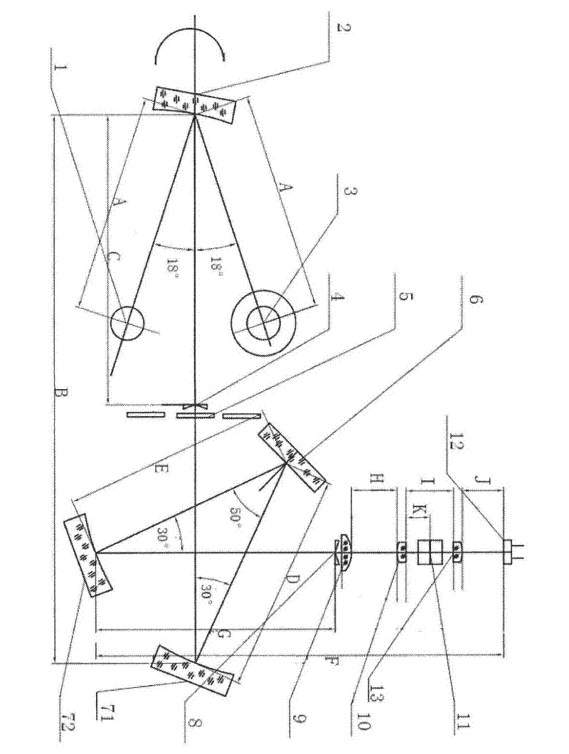
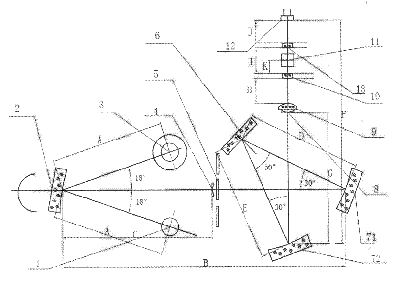
[0027] Such as figure 1 , is a schematic diagram of the optical path of the present invention. Light sources 1 and 3 project light onto the light source mirror 2 to form an optical path. Light source 1 is an ultraviolet light source, and light source 3 is a visible light source. The length of the optical path from the center of the circle to the light source reflector 2 is A, and A is 90mm. The light source reflector 2 is a reflector with a radius of 100mm and a width of 10mm. The light path projected by the two light sources is focused and reflected into a horizontal straight line through the light source reflector 2 The length of the optical path is B, and B is 210mm. The length of the horizontal linear optical path from the light source reflector 2 to the slit 4 is C, and C is 110mm, and an optical filter 5 is also arranged in front of the slit 4 to achieve the lig...


PUM


Abstract

The invention discloses a light path of an ultraviolet visible spectrophotometer. The light path comprises a light source reflector for reflecting a light source into a horizontally linear light path, wherein a first reflector is arranged at the tail end of the horizontally linear light path and used for reflecting the horizontally linear light path into a 30-degree linear light path; a grating is arranged at the tail end of the 30-degree linear light path and used for reflecting the 30-degree linear light path into a 50-degree linear light path; and a second reflector is arranged at the end of the 50-degree linear light path and used for reflecting the 50-degree linear light path into a vertically linear light path vertical to the horizontally linear light path. The finally obtained vertically linear light path is a finally used light path; the light route is short, the energy loss is reduced, the energy is 5 to 10 times that of the conventional spectrophotometer, and the light spot is reduced by 4 to 5 times; the spectrophotometer can be used for analyzing 20 mu L of trace nucleic acid; and the generality is high.

Description

technical field [0001] The invention relates to an optical path design of an ultraviolet-visible spectrophotometer. Background technique [0002] UV-Vis spectrophotometer is used for qualitative and quantitative analysis of trace substances. The optical path design of the traditional UV-visible spectrophotometer makes the optical path of the monochromator and the sample chamber long, and the energy loss is large, resulting in low energy when testing the sample, and the test of high-concentration substances is limited; the optical path design of the traditional UV-visible spectrophotometer It makes it bulky, which is not conducive to normal placement in crowded laboratories; the optical path design of the traditional UV-Vis spectrophotometer makes the light spot passing through the sample longer, and the amount of sample required for the test is large, but nucleic acid samples are very precious, so it is not suitable A lot of waste; the optical path design of the traditional...

Claims


Application Information

Patent Timeline
Patent Type & Authority Applications(China)
IPC IPC(8): G01J3/02
Inventor 谢玉生韩明山邢新刚钱莹莹汪希文
Owner SHANGHAI METASH INSTR
Why Eureka
Try Eureka