Photoetching lamp optical system

An illumination optical system and lithography technology, applied in microlithography exposure equipment, optics, optical components, etc., can solve the problems of high price and high cost of microlens arrays

Inactive Publication Date: 2012-07-11
SHANGHAI MICRO ELECTRONICS EQUIP (GRP) CO LTD
View PDF3 Cites 15 Cited by
  • Summary
  • Abstract
  • Description
  • Claims
  • Application Information

AI Technical Summary

Problems solved by technology

When using a microlens array as a uniform light device, the number of microlenses is related to the uniformity of illumination. At present, the size of a single microlens in a microlens array can be made very small, which means that a microlens array of the same size The numbe

Method used


Image

  • Photoetching lamp optical system
  • Photoetching lamp optical system
  • Photoetching lamp optical system

Examples


no. 1 example

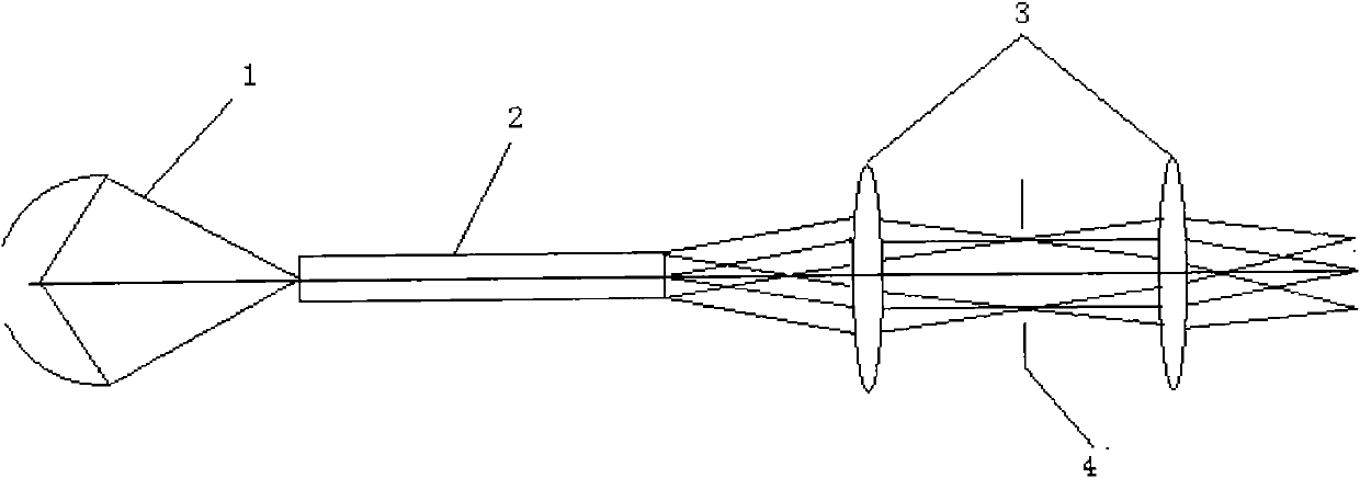
[0023] A specific example of the present invention is Figure 4 shown. The light emitted by the light source 100 is converged by the ellipsoidal reflector and irradiated on the uniformity enhancing element fly-eye lens 200. After passing through the fly-eye lens 200, the light beam enters the incident end surface 300a of the integrator rod 300, and the light beam is totally reflected in the integrator rod 300 for many times. Uniform illumination is formed on the exit end face 300b of the integrating rod. After being enlarged by the relay lens 400, the exit end face 300b of the integrating rod is imaged on the mask plate 600 through the aperture stop 500, and the required light with a certain numerical aperture, Size, uniformity of illumination field of view.

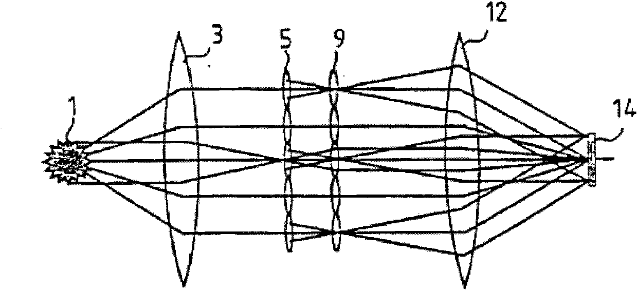
[0024] In this embodiment, the fly-eye lens 200 used by the uniformity enhancing element, such as Figure 5 shown.

no. 2 example

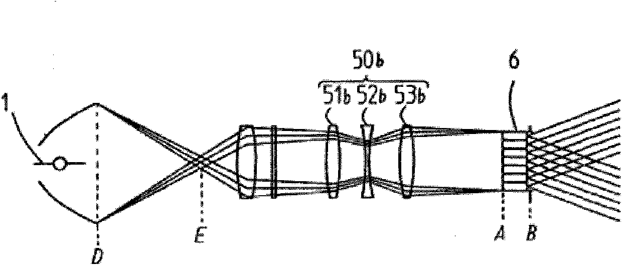
[0026] Another specific embodiment of the present invention is Figure 6 shown. The light emitted by the mercury lamp is converged by the ellipsoid reflector and passes through the coupling lens 700. The coupling lens 700 can change the numerical aperture of the light source 100 or keep the numerical aperture of the light source 100 unchanged. On the element microlens array 800, the light beam enters the incident end surface 300a of the integrator rod 300 through the microlens array 800, and after the light beam is totally reflected in the integrating rod 300 for many times, uniform illumination is formed on the exit end surface 300b of the integrating rod, and the exit end surface 300b of the integrating rod After being magnified by the relay lens 400 , the image is imaged on the mask plate 600 , and a required illumination field of view with a certain numerical aperture, size and uniformity is formed on the mask plate 600 .

[0027] In this embodiment, the uniformity enhanc...


PUM


Abstract

The invention relates to a photoetching lamp optical system, which comprises a light source, an integral rod, a relay lens and a mask, and is characterized by also comprising a uniformity strengthening component. According to the photoetching lamp optical system, the uniformity strengthening component is added in an incident end of the integral rod, so that the illumination uniformity can be greatly improved under the condition that the integral rod is shorter. Simultaneously, the cost can be reduced, the size of a machine is decreased, and the difficulty in assembly is reduced.

Description

technical field [0001] The invention relates to the technical field of semiconductor manufacturing, in particular to a lithography illumination optical system of a lithography machine. Background technique [0002] In the existing photolithography method, the optical system using high-pressure mercury lamp illumination mainly exposes the three lines g(436nm)h(405nm)i(365nm) to obtain a certain pattern on the silicon wafer coated with photoresist. [0003] In order to achieve the required exposure dose and dose uniformity on the silicon wafer surface, not only the light intensity of the illumination system is required, but also the uniformity of light intensity, which is usually referred to as the non-uniformity of the illumination field of view. Integrator rods, microlens arrays, fly-eye lenses, etc. are usually used as uniform light devices in lighting systems. [0004] In the prior art, an integrating rod or a microlens array is generally used alone as a uniform light dev...

Claims


Application Information

Patent Timeline
IPC IPC(8): G03F7/20G02B27/00G02B27/09G02B3/00
Inventor 胡斌
Owner SHANGHAI MICRO ELECTRONICS EQUIP (GRP) CO LTD
Why Eureka
Try Eureka