
Current balancing circuit with multi-path output

A technology of current balance and rectifier circuit, which is applied in lamp circuit layout, output power conversion device, load balance in DC network, etc., can solve the problems of optimization improvement, large forward voltage drop of diodes, and increased withstand voltage of rectifier devices. , to achieve the effect of saving volume and cost, simple circuit structure and improving conversion efficiency

Inactive Publication Date: 2012-07-11
SILERGY SEMICON TECH (HANGZHOU) CO LTD
View PDF2 Cites 5 Cited by
  • Summary
  • Abstract
  • Description
  • Claims
  • Application Information

AI Technical Summary

Problems solved by technology

The LLC resonant DC converter has high conversion efficiency and is currently widely used in LED drive applications. Its principle block diagram is as follows: figure 1 As shown, the two rectification circuits corresponding to the secondary winding pass through the DC blocking capacitor C 1 To achieve current balance without any active components and active control, but this can only achieve current balance between the same secondary winding and two LED strings. When there are too many LEDs in series, the LED string terminal voltage If it is too high, the withstand voltage on the rectifier device will increase, and the diode with high withstand voltage has a large forward voltage drop, and its conduction loss and reverse recovery loss cannot be ignored, so it is difficult to further optimize and improve the conversion efficiency of the entire system
In addition, because the filter capacitor needs to use a large-capacity capacitor with high withstand voltage, the design and production costs are increased.

Method used


Image

  • Current balancing circuit with multi-path output
  • Current balancing circuit with multi-path output
  • Current balancing circuit with multi-path output

Examples


Embodiment Construction

[0024] Several preferred embodiments of the present invention will be described in detail below with reference to the accompanying drawings, but the present invention is not limited to these embodiments. The present invention covers any alternatives, modifications, equivalent methods and schemes made on the spirit and scope of the present invention. In order to provide the public with a thorough understanding of the present invention, specific details are set forth in the following preferred embodiments of the present invention, but those skilled in the art can fully understand the present invention without the description of these details.

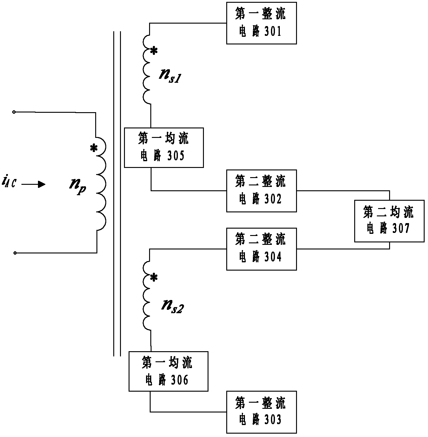
[0025] refer to image 3 , shows the functional block diagram of the first embodiment of the current balancing circuit with multiple outputs according to the present invention, which includes a transformer, and the transformer includes a primary winding n p and two secondary windings n s1 , n s2 .

[0026] The primary winding n p rec...


PUM


Abstract

The invention relates to a current balancing circuit with multi-path output, wherein a first flow equalizing element is used for carrying out flow equalization to two corresponding rectification circuits of a same auxiliary side winding, and a second flow equalizing element is used for carrying out flow equalization to current between different auxiliary side windings so as to realize output current balancing among multiple rectification circuits, and simultaneously, additional active devices and control are not needed. The current balancing circuit is applicable to the condition that an auxiliary side has multiple windings, and the current balance among multiple paths of output is realized by the characteristics of the flow equalizing elements. Even in application occasions with high power, low voltage resistant rectifying diodes and filter capacitors can meet the requirement, therefore, the conversion efficiency of the whole system is improved, volume and cost are saved due to the adoption of the filter capacitor with small capacity, and simultaneously, the circuit is simple in structure and easy to realize. The current balancing circuit is suitable for power supply occasions needing multiple equal current outputs and is especially applicable to LED (light-emitting diode) drivers with multiple paths of output.

Description

technical field [0001] The invention relates to a circuit with multiple outputs, in particular to a current balance circuit with multiple outputs. Background technique [0002] At present, when LEDs are used in occasions requiring high-power and high-brightness lighting, multiple LED strings are often used in combination. The brightness of an LED is directly related to the amount of forward current flowing through it: generally speaking, the greater the forward current flowing through the LED, the greater its brightness will be. In order to achieve brightness balance of multiple LEDs, it is usually necessary to precisely balance the forward currents flowing through multiple LED strings. The LLC resonant DC converter has high conversion efficiency and is currently widely used in LED drive applications. Its principle block diagram is as follows: figure 1 As shown, the two rectification circuits corresponding to the secondary winding pass through the DC blocking capacitor C ...

Claims


Application Information

Patent Timeline
IPC IPC(8): H02M7/06H05B37/02H05B44/00
CPCH05B37/02H02M3/00H05B33/0809H02J1/14H02M3/338H05B45/35
Inventor 赵晨余峰
Owner SILERGY SEMICON TECH (HANGZHOU) CO LTD
Features
  • Generate Ideas
  • Intellectual Property
  • Life Sciences
  • Materials
  • Tech Scout
  • Unparalleled Data Quality
  • Higher Quality Content
  • 60% Fewer Hallucinations
Learn More