

Antireflective transparent emi shielding optical filter
A filter, transparent technology, applied in the direction of optics, optical components, magnetic/electric field shielding, etc., can solve the problems of high production cost, image transmission loss, increased cost, etc.
Inactive Publication Date: 2012-07-11
3M INNOVATIVE PROPERTIES CO
View PDF35 Cites 6 Cited by
- Summary
- Abstract
- Description
- Claims
- Application Information
AI Technical Summary
Problems solved by technology
The use of multiple optical filters in an electronic device to achieve the desired performance characteristics adds cost, creates bulky devices, and causes considerable loss of the desired image in transmission
Method used
View moreImage
Smart ImageViewing Examples

Examples
example
[0074] Table 1
[0075] Materials for each instance
[0076]
[0077] All examples and comparative examples were prepared using a multi-zone vacuum chamber comprising a roll-to-roll web handling system that allows for sequential coating and / or treatment processes: including plasma treatment, e-beam treatment, Sputter coating, and vapor coating. Generally, sequential coating is used to deposit two different materials during a single pass through the chamber. Coils run forward unless otherwise specified. A schematic diagram of the coating system is shown in Figure 9 and with that disclosed in, for example, U.S. Patent No. 7,351,479 (Fleming et al.) Figure 6 The coating system in A is basically the same.
Login to View More PUM
| Property | Measurement | Unit |
|---|---|---|
| thickness | aaaaa | aaaaa |
| thickness | aaaaa | aaaaa |
| thickness | aaaaa | aaaaa |
Abstract
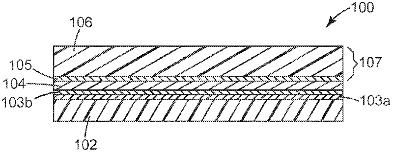
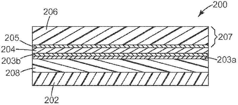
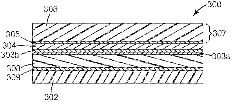
Antireflective transparent EMI shielding optical filters are provided that can be laminated to optical display devices using optically clear adhesives. The provided filters include electrically-conductive metal or metal alloy layers that can be continuous and patterned or unpatterned. Also included are methods of making the provided filters and touch sensors made using the provided filters.
Description
technical field [0001] The present invention provides multicomponent films that can be used as optically transparent display filters on electronic devices. Background technique [0002] The use of electronic devices including flat panel displays is very popular and increasing at an accelerating rate. These electronic devices include, for example, flat panel displays including electroluminescence (EL) lamps, light emitting diodes (LEDs), organic light emitting diodes (OLEDs), or liquid crystal displays. Most of these displays require multiple filters to adjust the display's performance characteristics, including neutrality and transmitted color levels, reflected radiation levels, and transmission levels of unwanted near-infrared and electromagnetic interference (EMI) radiation. [0003] Optical filters with EMI shielding have been developed that modify visible radiation, modify infrared radiation, adjust color, reduce reflection, and protect the viewer from harmful (EMI) rad...
Claims
Login to View More Application Information
Patent Timeline
 Patent Type & AuthorityApplications(China)
IPC IPC(8): H05K9/00G02B1/11
CPCG02B1/116G02B5/207
Inventor克拉克·I·布莱特罗伯特·C·菲策尔约翰·D·黎
Owner3M INNOVATIVE PROPERTIES CO