Guide track unloading device for crossbeam of large-sized machine tool and deflection compensation method

An unloading device, beam technology, applied in metal processing machinery parts, other manufacturing equipment/tools, maintenance and safety accessories, etc., can solve the problems of beam reference guide rail deformation, deflection deformation, inability to effectively compensate beam deflection deformation, etc. , to achieve stable and reliable operation

Active Publication Date: 2012-07-18
ZHEJIANG YIFENG MACHINERY
View PDF7 Cites 12 Cited by
  • Summary
  • Abstract
  • Description
  • Claims
  • Application Information

AI Technical Summary

Problems solved by technology

[0003] In order to meet the processing of key components such as the pressure shell of the large-scale key parts of the pressurized water reactor nuclear power of the million-kilowatt class, a special-purpose single-column mobile vertical turning-milling compound processing machine tool for super-large specifications has emerged as the times require. Machining accuracy, the rigidity of the ultra-long cantilever beam also needs to be greatly enhanced, and the self-weight of the transverse slide plate and ram milling head also increases significantly, resulting in a series of problems: 1. The super-long cantilever (simply supported) beam is produced due to its own weight Deflection and deformation cause the deformation of the beam reference rail; 2. The self-weight of the transverse slide plate and ram milling head are all loaded on the beam reference rail, increasing the load on the beam guide rail, causing the beam reference rail to deform; 3. When the machine tool is running, with As the running distance of the horizontal slide increases, the pressure between the horizontal slide and the support surface of the beam reference guide rail increases, and the friction force increases accordingly, which increases the additional load of the machine tool, aggravates the wear of the insert, and affects the running accuracy of the machine tool
Its shortcoming is that the beam is required to have sufficient rigidity, and the deflection deformation of the beam cannot be effectively compensated.
[0008] The second method is a compensation and unloading method that is widely used at present, which can effectively reduce the load carried by the reference guide rail of the beam and improve the straightness of the movement of the tool holder slide on the beam; its disadvantages are: unloading The structure of the device is complex, and it is difficult to process the convex shape on the upper surface of the unloading beam; the size of the unloading force is determined by the spring preload and the spring compression during operation, and cannot be adjusted according to the stiffness of the beam itself. The volume adjustment operation is difficult, and during use, the problem of damage to the spherical roller bearing due to excessive unloading force often occurs

Method used


Image

  • Guide track unloading device for crossbeam of large-sized machine tool and deflection compensation method
  • Guide track unloading device for crossbeam of large-sized machine tool and deflection compensation method
  • Guide track unloading device for crossbeam of large-sized machine tool and deflection compensation method

Examples


Embodiment Construction

[0027] Below in conjunction with accompanying drawing, the present invention is further described:

[0028] A method for deflection compensation and guide rail unloading compensation for beams of large machine tools, characterized in that the specific steps are as follows:

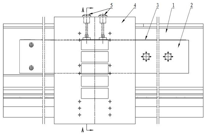
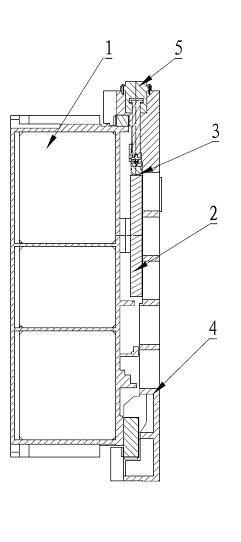
[0029] 1) Determination of compensation distance and compensation point: According to the deflection and deformation of the cantilever (simply supported) beam, through theoretical calculation, according to the principle of slope approximation, the unloading beam 2 is divided into several compensation distances, and the distance between adjacent compensation points According to the straight line processing, and the cross-section of the upper surface of the unloading beam 2 is composed of several straight lines, the upper surface of the unloading beam 2 is processed according to the value determined by the calculation result;

[0030] 2) Determination of the electrical compensation value: collect the straigh...


PUM


Abstract

The invention relates to the technical field of large-sized machine tools, in particular to a deflection compensation and guide track unloading compensation method for a crossbeam of a large-sized machine tool and a guide track unloading device. The action of unloading oil cylinders is controlled by a convex surface of the upper surface of an unloading beam and electro-hydraulic proportional pressure valves, the unloading beam on the crossbeam moves on a transverse slide plate, the full stroke of the movement of the unloading beam is determined by means of theoretical computation and is divided into a plurality of compensation intervals, straightness compensation points and straightness variation of the compensation intervals are acquired by experiments and converted into pressure setting values of the left unloading oil cylinder and the right unloading oil cylinder, electric signal values corresponding to the pressure setting values of the left unloading oil cylinder and the right unloading oil cylinder are inputted into a numerical control system of the machine tool, straightness errors of the transverse slide plate is automatically compensated by means of acquiring the electric signals corresponding to the pressure setting values of the left unloading oil cylinder and the right unloading oil cylinder by the control system, pressure on a support surface of a reference guide track of the crossbeam is reduced, the reference guide track of the crossbeam is stressed uniformly, deformation of the crossbeam is reduced, and integral precision of running of the machine tool is enhanced.

Description

technical field [0001] The invention relates to the technical field of large machine tools, in particular to a guide rail unloading device and a deflection compensation method for a beam of a large machine tool. Background technique [0002] With the continuous increase and upgrading of product specifications in nuclear power, mining, and heavy machinery industries, the demand for large-scale and heavy-duty processing equipment is extremely urgent. The large-scale and heavy-duty processing equipment will cause many technical problems to be solved. Among them, the deflection compensation of the beam of the large single-column vertical car and the unloading of the guide rail are key technologies that need to be solved urgently, which directly affects the main accuracy of the large single-column vertical car. [0003] In order to meet the processing of key components such as the pressure shell of the large-scale key parts of the pressurized water reactor nuclear power of the m...

Claims


Application Information

Patent Timeline
Patent Type & Authority Applications(China)
IPC IPC(8): B23Q11/00B23Q23/00
Inventor 张建州车忠伟汤鹏郑洪森王斌
Owner ZHEJIANG YIFENG MACHINERY
Why Eureka
Try Eureka