
Heat insulation structure of solar thermal power generation high-temperature molten salt storage tank and preparation method for heat insulation structure

A technology for high-temperature molten salt storage tanks and solar thermal power generation, which is applied in thermal insulation, thermal insulation containers, heat exchange equipment, etc., can solve the problems of accelerated thermal convection, reduced energy utilization rate of solar thermal power generation energy storage system, and increased heat loss, etc. Achieve the effect of prolonging service life, excellent reflection and reducing heat consumption

Inactive Publication Date: 2012-07-18
江苏太阳宝新能源有限公司
View PDF6 Cites 11 Cited by
  • Summary
  • Abstract
  • Description
  • Claims
  • Application Information

AI Technical Summary

Problems solved by technology

As we all know, heat is exchanged through three basic forms: heat conduction, heat convection, and heat radiation. Wind and sand weather makes the heat convection of the energy storage system in the solar thermal power generation faster, and the heat loss increases, thereby reducing the energy consumption of the solar thermal power generation energy storage system. utilization rate

Method used


Image

  • Heat insulation structure of solar thermal power generation high-temperature molten salt storage tank and preparation method for heat insulation structure
  • Heat insulation structure of solar thermal power generation high-temperature molten salt storage tank and preparation method for heat insulation structure
  • Heat insulation structure of solar thermal power generation high-temperature molten salt storage tank and preparation method for heat insulation structure

Examples


Embodiment 1

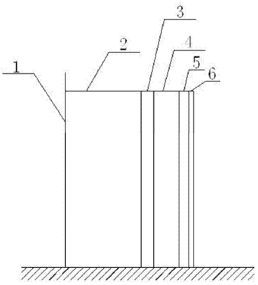
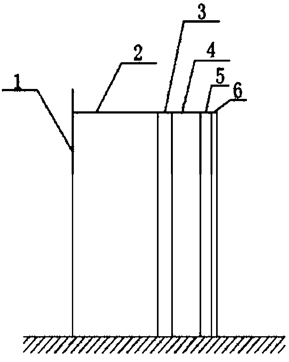
[0025] Such as figure 1 As shown, the heat insulation layer 2 is made of aluminum silicate fiber blanket with a thickness of 5 cm, which is constructed by bundling method on the storage tank 1, and the bundling distance is 20 cm. A 10mm circumferential expansion joint is left in the heat insulation layer 2 structure, which is filled and smoothed with aluminum silicate fiber. The heat insulation layer 2 is laid layer by layer, with staggered seams in the same layer, and the inner and outer layers are laid by pressing seams, bundled layer by layer, and the surface of each layer is leveled and seamed.

[0026] The reflective layer 3 is made of smooth aluminum foil with a thickness of 0.05 mm, which is evenly and evenly pasted on the surface of the heat insulating layer 2 by using a high-temperature adhesive.

[0027] 100mm away from the outer side of the reflective layer 3, with the center of the storage tank as the center, set 40×40×3mm angle steel evenly and vertically at 30°,...

Embodiment 2

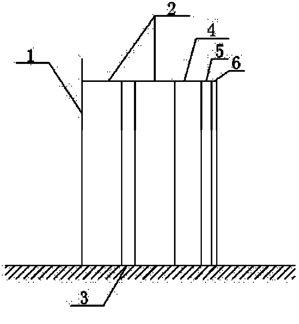
[0030] Such as figure 2 As shown, the material of the thermal insulation layer 2 is silica airgel with a thickness of 1 cm, which is constructed by bundling method, and the bundling distance is 20 cm. There is a 10mm circumferential expansion joint in the heat insulation layer structure, which is filled and smoothed with airgel fibers. The heat insulation layer is laid layer by layer, with staggered seams in the same layer, and the inner and outer layers are laid by pressing seams, bundled layer by layer, and the surface of each layer is leveled and seamed.

[0031] The reflective layer 3 is made of 0.05mm thick smooth stainless steel foil, which is pasted on the surface of the airgel evenly and evenly in advance with a high-temperature adhesive, and placed in the middle of the heat insulating layer.

[0032] 100mm away from the outer side of the insulation layer, with the center of the storage tank as the center, set 40×40×3mm angle steel evenly and vertically at 45°, and t...


PUM


Abstract

The invention relates to a heat insulation structure of a solar thermal power generation high-temperature molten salt storage tank, which comprises a heat insulation layer, a reflecting layer, a composite functional layer and a protective layer. The reflecting layer is a polished aluminum foil (plate) or a stainless steel foil (plate), and the composite functional layer is made of phenolic aldehyde, polyurethane or tripolycyanamide by means of integral foaming. The invention further provides a preparation method for the heat insulation structure and application of the heat insulation structure. The heat insulation layer and the reflecting layer are constructed layer by layer, a support ring of the protective layer is machined according to the shape of the storage tank, and the protective layer serves as a formwork for casting the composite functional layer, so that the heat insulation structure of the storage tank is formed. The heat insulation structure of the storage tank is excellent in heat insulation effect and long in service life.

Description

technical field [0001] The invention relates to a high-temperature energy storage technology for solar thermal power generation, in particular to a technology for a thermal insulation structure in a high-temperature molten salt energy storage system for solar thermal power generation. Background technique [0002] The depletion of fossil energy and the deteriorating environment have become long-term and major bottlenecks restricting the development of the global economy and society, and affecting the living conditions of human beings. In order to solve this problem, on the one hand, it is necessary to make scientific, economical, efficient use and development of fossil fuels, and on the other hand, it is necessary to accelerate the development and utilization of renewable energy. Solar energy has attracted widespread attention due to its wide distribution and abundant reserves. Vigorously developing and utilizing solar energy will change my country's energy shortage and unr...

Claims


Application Information

Patent Timeline
IPC IPC(8): B65D90/02B65D81/38F16L59/02F16L59/08
Inventor 何毅刘平心张雷刘国敏郭廷伟刘明松殷建平田洪增
Owner 江苏太阳宝新能源有限公司
Learn More