
Efficient radiating intelligent frying kitchen range

A cooking stove, intelligent technology, applied in household stoves, household heating, heating fuel, etc., can solve the problems of air volume loss, scattered heat dissipation, uneven heat dissipation, etc., to reduce the occupation of upper and lower space, increase the air flow, Effect of reducing air volume loss

Active Publication Date: 2012-07-18
HONGYANG HOME APPLIANCES
View PDF6 Cites 2 Cited by
  • Summary
  • Abstract
  • Description
  • Claims
  • Application Information

AI Technical Summary

Problems solved by technology

The above-mentioned electromagnetic cooking device will produce the following problems when dissipating heat: 1. Since the heating element on the circuit board is currently the main object of heat dissipation, the circuit board is generally located between the air inlet and the air outlet on the housing, but the above-mentioned heat dissipation is affected by the housing. The internal space is greatly affected, and it is easy to form an internal heat dissipation dead angle. Part of the air flow forms a vortex in the casing. Due to the use of the suction fan, there will be a certain wind pressure inside the machine, resulting in air loss, low utilization of heat dissipation air volume, and heat dissipation. Scattered, poor cooling effect
Taking the existing electromagnetic cooker as an example, the air inlet is set at the bottom of the lower shell, and the air outlet is set outside the shell. The excessively long heat dissipation circulation channel produces the above-mentioned problems of eddy current and air volume loss; in addition, the axial flow in the electromagnetic cooker The direction of the heat dissipation air inhaled by the fan is usually along the axial direction, and most of the heat dissipation air entering the induction cooker from the bottom of the shell will blow vertically upward along the axial direction of the axial flow fan. It is misplaced with the air inlet in the horizontal direction, which will cause further loss of air volume, and the cooling effect of the heating components on the circuit board will not be obvious
2. When the electromagnetic wire reel of the electromagnetic cooking device is a concave wire reel, and when the circuit board and the electromagnetic wire reel are dissipated at the same time, the wind blowing from a single direction to the bottom of the concave reel will cause some wire reels to dissipate heat quickly. However, other parts of the wire reel have slow heat dissipation and even no wind blowing. Take the IH rice cooker as an example, the concave wire reel will cause uneven heat dissipation.
[0003] However, whether it is an IH rice cooker or a concave induction cooker, the concave electromagnetic wire tray will take up more space, which increases the upper and lower space of the cooker, and the concave induction cooker adopts the axial flow fan, due to the axial flow fan. The thickness limit will further increase the upper and lower space of the concave induction cooker, which will increase the thickness of the existing concave induction cooker, making the whole relatively bulky, which does not meet the needs of users for portability
[0004] In addition, for the electromagnetic cooking device with bottom air inlet and side air outlet, the structure of side air outlet will easily cause water to enter the electromagnetic cooking device along the side heat dissipation port, resulting in potential safety hazards; , will destroy the overall shape of the product, so this type of product has a tendency to be gradually eliminated by the market
Due to the above-mentioned technical defects in the electromagnetic cooking device, the marketing of this type of product has been affected
[0005] The technical defects of heat dissipation and airflow and the overall structure of the above-mentioned electromagnetic cooking device not only limit the market scale of this high-energy-efficiency, low-pollution electromagnetic cooking device, especially the current market is highly concerned about product safety, energy efficiency and portability. Improvement of existing electromagnetic cooking devices is imminent

Method used


Image

  • Efficient radiating intelligent frying kitchen range
  • Efficient radiating intelligent frying kitchen range
  • Efficient radiating intelligent frying kitchen range

Examples


Embodiment 1

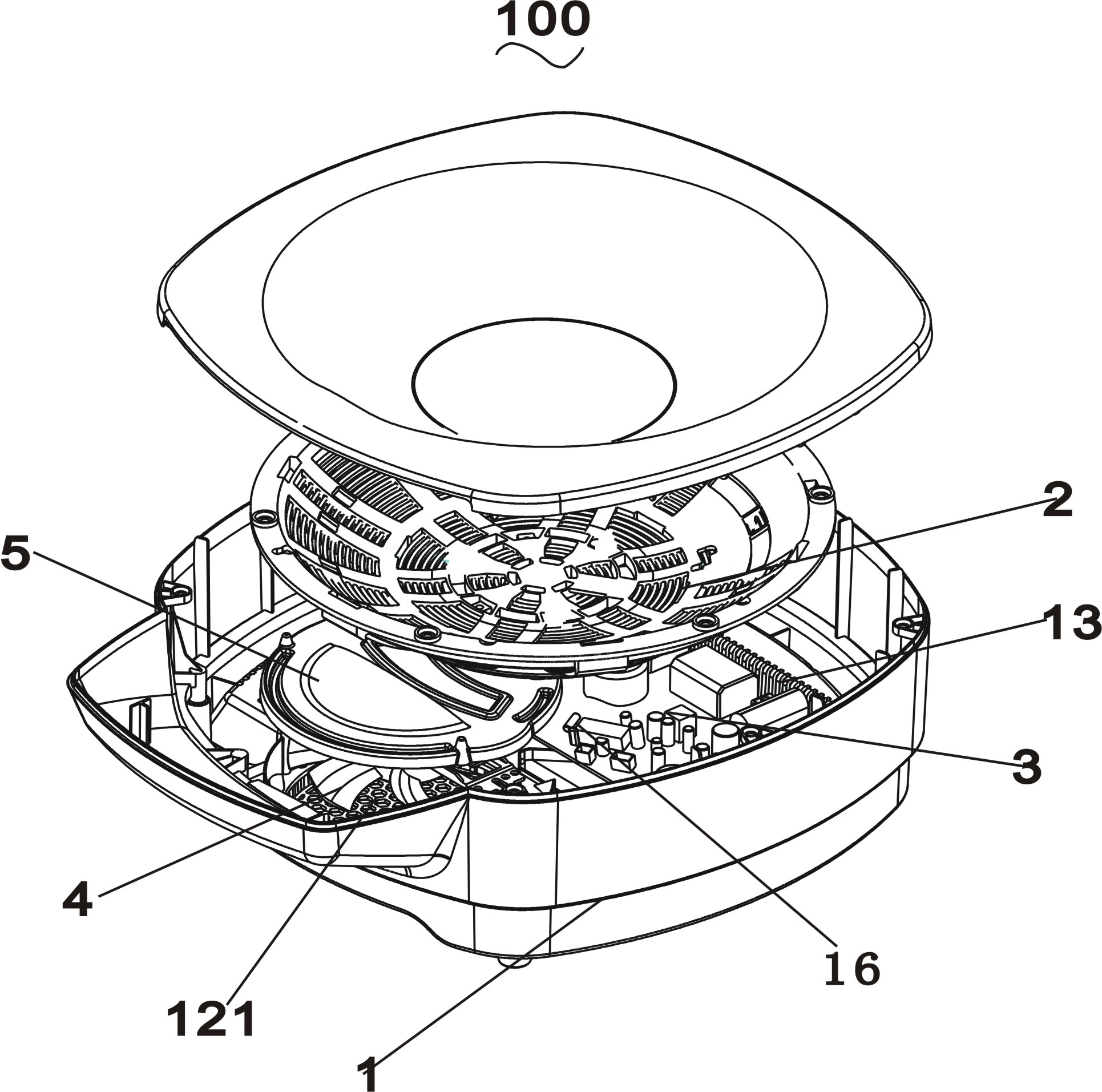
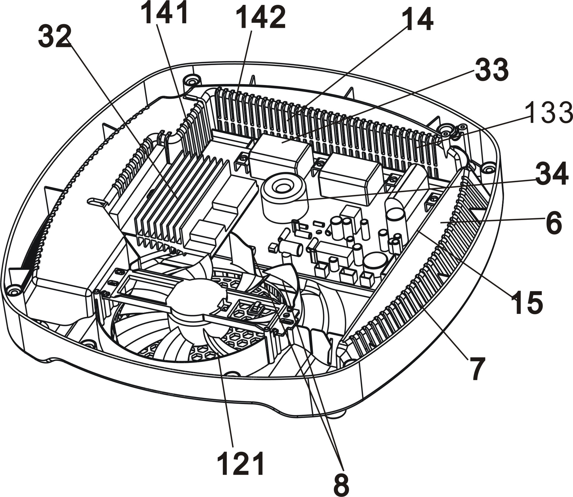
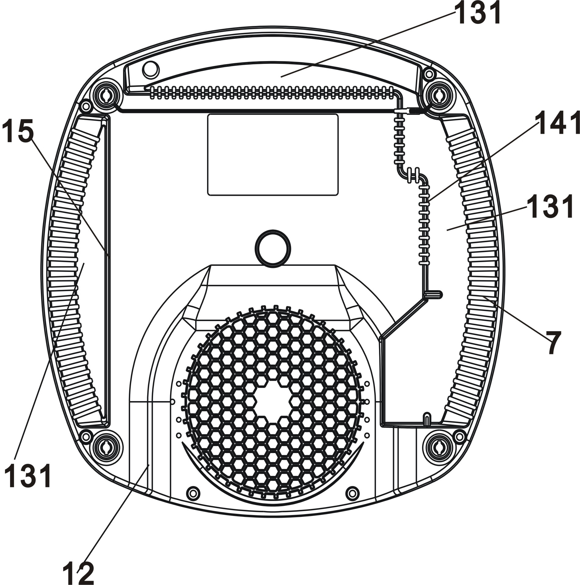
[0046] Such as Figure 1-6As shown, it is an intelligent cooking stove 100 with efficient heat dissipation of the present invention, which includes a housing 1, an electromagnetic wire reel 2, a circuit board 3 and a cooling fan 4, the circuit board 3 is provided with a heat release device, and the housing 1 includes a shell 11 and a bottom case 12, the bottom case 12 is provided with an air inlet 121 corresponding to the cooling fan 4, the housing 1 also includes a heat dissipation inner case 13 arranged inside the outer case 11, the heat dissipation inner case 13 includes an air outlet plate 14 and The wind deflector 15 and the wind outlet plate 14 are provided with an air outlet 133 communicating with the outside world, and the wind deflector 15 is connected with the air outlet plate 14 to form a heat dissipation space 16 . The heat dissipation devices on the circuit board 3 include an IGBT heat sink 32 , a resonant capacitor 33 , and an inductance element 34 and a relay ar...


PUM


Abstract

The invention discloses an efficient radiating intelligent frying kitchen range. The efficient radiating intelligent frying kitchen range comprises a shell, an electromagnetic wire coil, a circuit board and a radiating fan, wherein the electromagnetic wire coil is arranged in a concave mode; a heat emission device is arranged on the circuit board; the shell comprises an outer shell, a bottom shell and a radiating inner shell which is arranged on the inner side of the outer shell; an air inlet opposite to the radiating fan is formed in the bottom shell; the radiating inner shell comprises an air exhaust plate and an air baffle plate; an air outlet communicated with the outside is formed in the air exhaust plate; the air baffle plate is connected with the air exhaust plate to form a radiating space; and the circuit board is flatly spread in the radiating space. By the kitchen range, the circuit board in the radiating space can be effectively cooled in a concentrated mode; and the kitchen range is high in radiating efficiency.

Description

technical field [0001] The invention relates to the field of kitchen cooking utensils, in particular to an intelligent cooking range capable of realizing high-efficiency heat dissipation. Background technique [0002] The electromagnetic cooking device in the prior art generally includes a housing, an air inlet arranged on the housing, a cooling fan provided corresponding to the air inlet, and an air outlet. The housing is provided with an electromagnetic heating coil and a circuit board. The heat dissipation process is as follows: the heat dissipation air enters the casing from the air inlet, and after the heat dissipation air dissipates heat to the relevant heating elements of the electromagnetic cooking device, it is blown out of the electromagnetic cooking device from the air outlet. The above-mentioned electromagnetic cooking device will produce the following problems when dissipating heat: 1. Since the heating element on the circuit board is currently the main object o...

Claims


Application Information

Patent Timeline
IPC IPC(8): F24C7/00F24C15/00
Inventor 朱泽春李彬乔中义
Owner HONGYANG HOME APPLIANCES
Learn More